Sony F23 Product Manual (F23 Operation Manual 1st edition) - Page 14
Rear panel, MONITOR OUT HD SDI connectors 1/2 BNC
 |
View all Sony F23 manuals
Add to My Manuals
Save this manual to your list of manuals |
Page 14 highlights
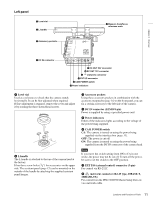
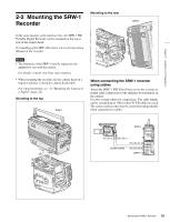
Rear panel Chapter 1 Overview a Safety release tab b Accessory clamp lever c Lock release knob d Accessory mount lever e Recorder/interface box receptacles 3 2 f RUN indicator and ON/OFF switch OFF ON g GENLOCK IN connector h TEST OUT connector i MONITOR OUT HD SDI connectors 1/2 REMOTE j REMOTE connector DC IN connector (see page 11) k Wrench box a Safety release tab b Accessory clamp lever c Lock release knob d Accessory mount lever For mounting/unmounting an SRW-1 HD Portable Digital Recorder or the interface box to/from the rear of the camera head. The mounting/unmounting mechanism is the same as that on the top (page 12). For details, see "Chapter 2 Installation and Preparations". e Recorder/interface box receptacles Signals and power are sent/received to/from an SRW-1 HD Portable Digital Recorder or the supplied interface box (page 15) mounted on the rear. The same receptacles are provided on the top to send/ receive signals and power to/from the recorder or the interface box mounted on the top. When using a rechargeable battery Use the receptacles on the rear panel. By attaching the BKP-L551 to the rear of the interface box, the camera can be operated on a battery. Note, however, that power will be fed only to the camera head and viewfinder. Provide another power source for the recorder. f RUN indicator and ON/OFF switch When the switch is set to ON, the indicator will be lit while the recorder mounted on the camera is in Recording mode. g GENLOCK IN (external sync signal input) connector (BNC type) Used for input of an external gen-lock signal (3-level sync). h TEST OUT connector (BNC type) An analog test signal is fed from the connector. The type of output signal can be set using a menu on the viewfinder or monitor screen. i MONITOR OUT HD SDI connectors 1/2 (BNC type) An HD SDI signal for monitoring is fed from the connectors. The type of output signal can be set using a menu on the viewfinder or monitor screen. The same signal is output from connector 1 and 2. j REMOTE connector (8-pin) Connect an external control device, such as the RM-B150/ B750 Remote Control Unit. k Wrench box A 3-mm wrench for attaching/detaching the handle and a 2.5-mm wrench for attaching/detaching the viewfinder shoe are accommodated. 14 Locations and Functions of Parts
-
 1
1 -
2
-
3
-
4
-
5
-
6
-
7
-
8
-
 9
9 -
 10
10 -
 11
11 -
 12
12 -
 13
13 -
 14
14 -
 15
15 -
 16
16 -
 17
17 -
 18
18 -
 19
19 -
20
-
21
-
22
-
23
-
24
-
25
-
26
-
27
-
28
-
29
-
30
-
31
-
32
-
33
-
34
-
35
-
36
-
37
-
38
-
39
-
40
-
41
-
42
-
43
-
44
-
45
-
46
-
47
-
48
-
49
-
50
-
51
-
52
-
53
-
54
-
55
-
56
-
57
-
58
-
59
-
60
-
61
-
62
-
63
-
64
-
65
-
66
-
67
-
68
-
69
-
70
-
71
-
72
-
73
-
74
-
75
-
76
-
77
-
78
-
79
-
80
-
81
-
82
-
83
-
84
-
85
-
86
-
87
-
88
-
89
-
90
-
91
-
92
-
93
-
94
-
95
-
96
-
97
-
98
-
99
-
100
-
101
-
102
 |
 |
