Sony F23 Product Manual (F23 Operation Manual 1st edition) - Page 13
Display/menu operation block, MENU SEL selection /ENTER dial
 |
View all Sony F23 manuals
Add to My Manuals
Save this manual to your list of manuals |
Page 13 highlights
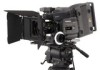
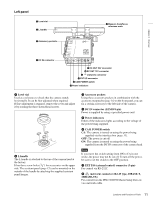
Chapter 1 Overview The mounting/unmounting mechanism is the same as that on the rear panel (page 14). For details, see "Chapter 2 Installation and Preparations". i Memory Stick section A slot to accommodate a "Memory Stick" is provided behind the rubber cap. The access lamp is lit in red while writing or reading data to/from a "Memory Stick." You can use the "Memory Stick PRO" or "Memory Stick PRO Duo" with this camera. The "Memory Stick PRO Duo" media can be used without any adaptor. Note When the access lamp is lit in red, do not insert/remove the "Memory Stick" or turn off the camera. For details, see "5-3-1 Using a "Memory Stick"" (page 81). j Focus reference mark Used as a reference for focusing. k Tripod receptacles (bottom) Two screw holes (for 3/8" camera screws) for tripod mounting are provided. Display/menu operation block Used to operate displays on the subdisplay and the viewfinder/monitor screen. For details on menu operations, see "3-2-1 Basic Operation of the Subdisplay" (page 27) and "4-2 Basic Menu Operations" (page 52). a Subdisplay For basic settings of this camera. When an SRW-1 HD Portable Digital Recorder has been docked, some statuses of the recorder can also be displayed. When the supplied assistant panel is connected, the same information will be displayed on the assistant panel. b VF (viewfinder) MENU/DISPLAY button Press this button to select the display mode of the subdisplay and the viewfinder (monitor) screen. c CANCEL/STATUS button In Menu Operation mode, press this button to cancel your entry or to resume the previous status. If you press this button when the menu is not displayed on the viewfinder (monitor) screen, the status information of the camera will be displayed. For the information displayed, see "3-6 Viewing and Setting the Viewfinder Displays" (page 39). d PAGE button Press this button to flip the pages or register the setting on the subdisplay. e SET button The subdisplay enters Data Change mode if you hold this button pressed for more than 1 second. Use this button also to flip to the previous page on the subdisplay. f MENU SEL (selection) /ENTER dial Used to select or set the items on the subdisplay or the menu items on the viewfinder (monitor) screen. a Subdisplay b VF MENU/DISPLAY button c CANCEL/STATUS button LOCK VF MENU/DISPLAY CANCEL/STATUS RUN 4 AUTO BLK BAL PAGE SET f MENU SEL/ENTER dial e SET button d PAGE button 13 Locations and Functions of Parts
-
 1
1 -
2
-
3
-
4
-
5
-
6
-
7
-
 8
8 -
 9
9 -
 10
10 -
 11
11 -
 12
12 -
 13
13 -
 14
14 -
 15
15 -
 16
16 -
 17
17 -
 18
18 -
19
-
20
-
21
-
22
-
23
-
24
-
25
-
26
-
27
-
28
-
29
-
30
-
31
-
32
-
33
-
34
-
35
-
36
-
37
-
38
-
39
-
40
-
41
-
42
-
43
-
44
-
45
-
46
-
47
-
48
-
49
-
50
-
51
-
52
-
53
-
54
-
55
-
56
-
57
-
58
-
59
-
60
-
61
-
62
-
63
-
64
-
65
-
66
-
67
-
68
-
69
-
70
-
71
-
72
-
73
-
74
-
75
-
76
-
77
-
78
-
79
-
80
-
81
-
82
-
83
-
84
-
85
-
86
-
87
-
88
-
89
-
90
-
91
-
92
-
93
-
94
-
95
-
96
-
97
-
98
-
99
-
100
-
101
-
102
 |
 |
