Sony F23 Product Manual (F23 Operation Manual 1st edition) - Page 23
Attaching/Detaching Handles, 2-6-1 L Handle, 2-6-2 Center Handle (Supplied), L Handle
 |
View all Sony F23 manuals
Add to My Manuals
Save this manual to your list of manuals |
Page 23 highlights
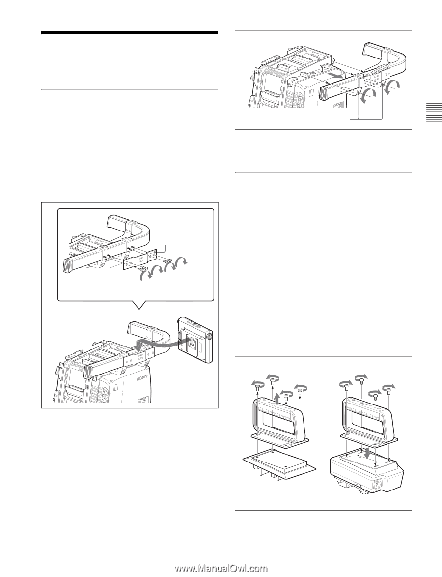
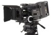
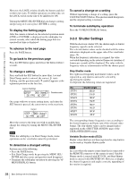
Chapter 2 Installation and Preparations 2 2 3 2 3 2 2-6 Attaching/Detaching Handles 2-6-1 L Handle The L handle is attached to the top of the camera head at the factory. Three screw holes (for 3/8" camera screws for a tripod) on the upper side of the L handle can be used for fixing various accessories. Mounting the assistant panel By attaching the supplied assistant panel hanger, you can mount the assistant panel on the outside of the handle. Assistant panel hanger (supplied) four +B4×8 screws (supplied) OFRFUONN GENLOCK IN TEST OUT Assistant panel Detaching the L handle If the L handle is not necessary or to be replaced with the supplied center handle, remove it by loosening the two screws, using the 3-mm wrench stored in the wrench box (page 14). OFRFUONN GENLOCK IN TEST OUT Hexagonal screws To attach the handle in the original position, reverse the procedure for detaching. 2-6-2 Center Handle (Supplied) The supplied center handle can be attached to the top or rear of the camera head. Attach it so that the slanting side faces the back (or bottom). The screw holes on the upper side of the handle can be used for fixing various accessories. Attaching the handle directly to the camera head The handle can be attached/detached in the same manner as the interface box (see page 17). Attaching the handle to the interface box mounted on the camera head First remove the base plate from the handle by loosening the four screws, then attach it to the interface box. Center handle 1 2 Base plate LOCK DC IN 10.5V-17V Interface box 23 Attaching/Detaching Handles
-
 1
1 -
2
-
3
-
4
-
5
-
6
-
7
-
8
-
9
-
10
-
11
-
12
-
13
-
14
-
15
-
16
-
17
-
 18
18 -
 19
19 -
 20
20 -
 21
21 -
 22
22 -
 23
23 -
 24
24 -
 25
25 -
 26
26 -
 27
27 -
 28
28 -
29
-
30
-
31
-
32
-
33
-
34
-
35
-
36
-
37
-
38
-
39
-
40
-
41
-
42
-
43
-
44
-
45
-
46
-
47
-
48
-
49
-
50
-
51
-
52
-
53
-
54
-
55
-
56
-
57
-
58
-
59
-
60
-
61
-
62
-
63
-
64
-
65
-
66
-
67
-
68
-
69
-
70
-
71
-
72
-
73
-
74
-
75
-
76
-
77
-
78
-
79
-
80
-
81
-
82
-
83
-
84
-
85
-
86
-
87
-
88
-
89
-
90
-
91
-
92
-
93
-
94
-
95
-
96
-
97
-
98
-
99
-
100
-
101
-
102
 |
 |