Sony HVRZ7P Operating Guide - Page 134
To attach the lens mount cap, To remove the, lens mount cap, Video control buttons STOP/REW
 |
View all Sony HVRZ7P manuals
Add to My Manuals
Save this manual to your list of manuals |
Page 134 highlights
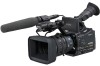
Identifying parts and controls (Continued) 7 8 9 TC/U-BIT DATA CODE 0 qa qh qg qf qd qs 12 3 4 MANUAL ZOOM SERVO 5 6 A Lens cover lever (13) B Focus ring (28) C Zoom ring (27) D Iris ring (30) E ZOOM switch (27) F DIGITAL EXTENDER/L1 button (43) G LCD screen (18) H TC/U-BIT button Switches between time code and user bit to display on the LCD screen. I DATA CODE button (53) J Video control buttons (STOP/REW/ PLAY/FF/PAUSE/REC/SLOW) (50) K VOLUME/MEMORY button (50) L MEMORY/DELETE button (50) M MEMORY/INDEX button (50) N MEMORY/PLAY button (50) O DISPLAY/BATT INFO button (53) P RESET button If you press the RESET button, all settings including the clock setting (except the Picture profile and Camera profile settings) return to the default. To attach the lens mount cap Hold the lens mount cap with the v mark facing up. Attach the lens mount cap to the lens mount with the center pin on the back of the cap inserted in the recess at the top center of the lens mount. To remove the lens mount cap Hold the protrusion at the center of the lens mount cap and remove the cap from the lens mount. 134 To attach the rear lens cap Attach the rear lens cap to the rear of the lens. To remove the rear lens cap Hold the two protrusions on the edge of the rear lens cap as illustrated and remove the cap from the lens.
-
 1
1 -
2
-
3
-
4
-
5
-
6
-
7
-
8
-
9
-
10
-
11
-
12
-
13
-
14
-
15
-
16
-
17
-
18
-
19
-
20
-
21
-
22
-
23
-
24
-
25
-
26
-
27
-
28
-
29
-
30
-
31
-
32
-
33
-
34
-
35
-
36
-
37
-
38
-
39
-
40
-
41
-
42
-
43
-
44
-
45
-
46
-
47
-
48
-
49
-
50
-
51
-
52
-
53
-
54
-
55
-
56
-
57
-
58
-
59
-
60
-
61
-
62
-
63
-
64
-
65
-
66
-
67
-
68
-
69
-
70
-
71
-
72
-
73
-
74
-
75
-
76
-
77
-
78
-
79
-
80
-
81
-
82
-
83
-
84
-
85
-
86
-
87
-
88
-
89
-
90
-
91
-
92
-
93
-
94
-
95
-
96
-
97
-
98
-
99
-
100
-
101
-
102
-
103
-
104
-
105
-
106
-
107
-
108
-
109
-
110
-
111
-
112
-
113
-
114
-
115
-
116
-
117
-
118
-
119
-
120
-
121
-
122
-
123
-
124
-
125
-
126
-
127
-
128
-
 129
129 -
 130
130 -
 131
131 -
 132
132 -
 133
133 -
 134
134 -
 135
135 -
 136
136 -
 137
137 -
 138
138 -
 139
139 -
140
-
141
-
142
-
143
 |
 |
