Sony MHC-NX1 Service Manual
Sony MHC-NX1 Manual
 |
View all Sony MHC-NX1 manuals
Add to My Manuals
Save this manual to your list of manuals |
Sony MHC-NX1 manual content summary:
- Sony MHC-NX1 | Service Manual - Page 1
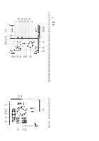
MHC-NX1/NX3AV TUNER,AMPLIFIER MHC-NX1 STR-NX1 MHC-NX3AV STR-NX3 Tourist Model MHC-NX1 CD PLAYER ,TAPE DECK FRONT SPEAKER SYSTEM CENTER/REAR SPEAKER SYSTEM HTC-NX1 SS-NX1 SS-RC100 HCD-NX1 is composed of STR-NX1 and HTC-NX1. HCR-NX3 is composed of STR-NX3 and HTC-NX1. PARTS LIST Ref. No. Part - Sony MHC-NX1 | Service Manual - Page 2
STR-NX1/NX3 SERVICE MANUAL US Model Canadian Model AEP Model UK Model E Model Australian Model Tourist Model STR-NX1/NX3 are the Tuner and Amplifier Section in MHC-NX1/NX3AV. Photo: STR-NX3 E model SPECIFICATIONS MICROFILM - Continued on next page - TUNER/AMPLIFIER - Sony MHC-NX1 | Service Manual - Page 3
MARK 0 OR DOTTED LINE WITH MARK 0 ON THE SCHEMATIC DIAGRAMS AND IN THE PARTS LIST ARE CRITICAL TO SAFE OPERATION. REPLACE THESE COMPONENTS WITH SONY PARTS WHOSE PART NUMBERS APPEAR AS SHOWN IN THIS MANUAL OR IN SUPPLEMENTS PUBLISHED BY SONY. 2 ATTENTION AU COMPOSANT AYANT RAPPORT À LA SÉCURITÉ! LES - Sony MHC-NX1 | Service Manual - Page 4
original service problem, perform the following safety check before releasing the set to the customer: Check the antenna terminals, metal trim, "metallized" knobs, screws, and all other exposed metal parts for AC leakage. Check leakage as described below. • MODEL IDENTIFICATION - Rear Panel - PART - Sony MHC-NX1 | Service Manual - Page 5
ANTENNA terminal 3 SYSTEM CONTROL connector 4 VIDEO (AUDIO) IN jacks 5 MD IN jacks 9 6 MD OUT jacks 7 DVD 5.1CH INPUT jacks (STR-NX3) 8 SUPER WOOFER OUT jack 9 VOLTAGE SELECTOR switch (Malaysia, Singapore and Tourist models) q; FRONT SPEAKER terminals qa REAR SPEAKER terminals qs CENTER - Sony MHC-NX1 | Service Manual - Page 6
This section is extracted from instruction manual. 5 - Sony MHC-NX1 | Service Manual - Page 7
SECTION 3 DISASSEMBLY Note: Follow the disassembly procedure in the numerical order given. CASE 3 case 1 two screws (case 3 TP2) 2 screw (BVTP3 × 10) FRONT PANEL ASS'Y 4 front panel ass'y 1 flat wire (CN132) 1 two screws (case 3 TP2) 3 claw 2 two screws (BVTT3 × 6) 3 claw 1 flat wire (CN131 - Sony MHC-NX1 | Service Manual - Page 8
BACK PANEL ASS'Y 2 connector (CN173) 5 back panel ass'y 3 seven screws (BVTP3 × 10) 1 flat wire (CN1) 4 claw 3 four screws (BVTP3 × 10) MAIN BOARD 4 claw 1 two connectors (CN161, 181) 1 connector (CN111) 4 main board 2 two screws (BVTP3 × 10) 3 connector (CN152) 7 - Sony MHC-NX1 | Service Manual - Page 9
to turn the power ON. 2. Press three buttons of [ENTER] , [DISPLAY] , and - m simultaneously. 3. "DVD 5.1CH" is displayed on liquid crystal display, and at the same time, CD is played and the deck B is placed in the record status. [CD Service Mode] • Execute only if connected to the HTC-NX1. • This - Sony MHC-NX1 | Service Manual - Page 10
the indicator of disc tray num- ber on the liquid crystal display is blinking. 7. To release from the aging mode, press the ?/1 button to turn the power OFF and operate the cold reset. (Refer to the "MC Cold Reset") 1. Display at the Aging Mode • Display operating state of CD section and tape deck - Sony MHC-NX1 | Service Manual - Page 11
Deck Section • The sequence during the aging mode is following as below. • If an error occurred, stop display that step. Aging mode sequence (Tape deck section) : Rewind the tape A and B "TAPE A AG -4" 2 minutes Rewind the tape B "TAPE B AG-5" Shut off Note: "TAPE * AG-*" is display of each step. 10 - Sony MHC-NX1 | Service Manual - Page 12
SCHEMATIC DIAGRAMS Note on Printed Wiring Board: • X : parts extracted from the component side. • Y : parts extracted from the conductor side. • x : parts PLAYBACK G : RECORD J : CD PLAY N : MIC INPUT • 5 REC IN 6 - + RESET C 7 BIAS C 8 GND 9 RESET 18 RESET BAND PASS FILTER DET 17 F01 - Sony MHC-NX1 | Service Manual - Page 13
STR-NX1/NX3 5-2. SCHEMATIC DIAGRAM - MAIN Board (1/3) - 12 12 (Page 13) (Page 19) (Page 17) (Page 14) - Sony MHC-NX1 | Service Manual - Page 14
5-3. SCHEMATIC DIAGRAM - MAIN Board (2/3) - • See page 11 for Waveforms. (Page 12) (Page 23) 13 13 STR-NX1/NX3 (Page 14) - Sony MHC-NX1 | Service Manual - Page 15
STR-NX1/NX3 5-4. SCHEMATIC DIAGRAM - MAIN Board (3/3) - • See page 11 for IC Block Diagram. (Page 12) (Page 13) 14 14 (Page 21) • Semiconductor Location Ref. No. D141 D216 D501 - Sony MHC-NX1 | Service Manual - Page 16
5-5. PRINTED WIRING BOARD - MAIN Board - • See page 11 for Circuit Boards Location. (Page 22) (Page 22) (Page 20) (Page 20) (Page 18) (Page 16) 15 15 STR-NX1/NX3 (Page 22) - Sony MHC-NX1 | Service Manual - Page 17
STR-NX1/NX3 5-6. PRINTED WIRING BOARD - SURROUND AMP Board - • See page 11 for Circuit Boards Location. • Semiconductor Location Ref. No. D101 D102 D151 D191 Location C-2 C-3 C-2 C-2 IC101 A-2 Q101 B-3 Q103 A-3 Q104 A-3 Q151 B-2 Q181 C-1 (Page 15) 16 16 (Page 18) - Sony MHC-NX1 | Service Manual - Page 18
5-7. SCHEMATIC DIAGRAM - SURROUND AMP Board - (NX3) STR-NX1/NX3 (Page 12) 17 17 (Page 19) The components identified by mark 0 or dotted line with mark 0 are critical for safety. Replace only with part number specified. Les composants identifiés par une marque 0 sont critiques pour la sécurit - Sony MHC-NX1 | Service Manual - Page 19
STR-NX1/NX3 5-8. PRINTED WIRING BOARD - PA Board - • See page 11 for Circuit Boards Location. (Page 15) (Page 22) (Page 16) 18 18 • Semiconductor Location Ref. No. - Sony MHC-NX1 | Service Manual - Page 20
5-9. SCHEMATIC DIAGRAM - PA Board - (Page 12) (Page 17) The components identified by mark 0 or dotted line with mark 0 are critical for safety. Replace only with part number specified. Les composants identifiés par une marque 0 sont critiques pour la sécurité. Ne les remplacer que par une pièce - Sony MHC-NX1 | Service Manual - Page 21
STR-NX1/NX3 5-10. PRINTED WIRING BOARDS - PANEL Section - • See page 11 for Circuit Boards Location. (Page 15) • Semiconductor Location Ref. No. D631 D632 D633 D636 D637 - Sony MHC-NX1 | Service Manual - Page 22
5-11. SCHEMATIC DIAGRAM - PANEL Section - STR-NX1/NX3 21 21 (Page 14) (Page 14) - Sony MHC-NX1 | Service Manual - Page 23
/NX3 5-12. PRINTED WIRING BOARDS - TRANSFORMER Section - • See page 11 for Circuit Boards Location. (MY, SP, JE / NX3:US, CND) (NX1:US, CND) JW953 • Semiconductor Location Ref. No. D952 D953 D954 D955 D956 D957 Location A-4 A-5 A-4 A-5 B-4 A-3 IC991 A-3 Q991 A-3 (Page 15) 22 22 (Page 15 - Sony MHC-NX1 | Service Manual - Page 24
5-13. SCHEMATIC DIAGRAM - TRANSFORMER Section - (Page 19) (Page 14) (Page 13) STR-NX1/NX3 (Page 14) 23 23 The components identified by mark 0 or dotted line with mark 0 are critical for safety. Replace only with part number specified. Les composants identifiés par une marque 0 sont critiques - Sony MHC-NX1 | Service Manual - Page 25
40 Hz) 3 F RELAY O Speaker protect relay drive signal output for the front side speaker "H": relay on 4 R RELAY O Speaker protect relay drive signal output for the rear side speaker "H": relay on 5 SIRCS I Remote control signal input from the remote control receiver (IC601) 6 LINE MUTE - Sony MHC-NX1 | Service Manual - Page 26
) 94 KEY0 I S601 to S614 (I/1, DISPLAY, POWER SAVE/DEMO (STANDBY), VIDEO/DVD, MD, TAPE, CD, TUNER, DSB, DBFB, PLAY MODE, REPEAT, EDIT, FILE SELECT) keys input 95 MODEL-IN I Destination setting terminal 96 AVSS - Ground terminal (for A/D conversion) 97 SPEC-IN I Setting terminal for the - Sony MHC-NX1 | Service Manual - Page 27
service. Some one. delay should be anticipated when ordering • Color Indication of Appearance Parts these items. Example: • The mechanical parts -355-1 PANEL ASSY, BACK (NX1: TH, KR) 3 X-4952-356-1 PANEL ASSY, BACK (NX3: AUS, KR) Ref. No. 4 5 6 6 6 Part No. Description Remark 1-773-011 - Sony MHC-NX1 | Service Manual - Page 28
NX1: AEP, UK) X-4951-815-1 PANEL ASSY, FRONT (NX1: E, JE) X-4951-816-1 PANEL ASSY, FRONT (NX3: E, AUS) Ref. No. 60 61 62 * 63 64 Part NX1: US, CND, AEP, UK) 55 4-221-380-11 PANEL (ST) (NX1 NX1) 58 4-221-377- NX1: US, CND, AEP, UK) 65 A-4426-249-A PANEL BOARD, COMPLETE (NX1 (NX1: TH - Sony MHC-NX1 | Service Manual - Page 29
(3) CHASSIS SECTION US, CND, AEP, UK 108 #3 #3 101 #5 #2 not supplied #5 #5 103 NX3 not supplied #6 #6 TR951 not supplied #5 not supplied #2 105 A #6 102 106 #1 109 JE 104 MY, SP 104 UK US, CND 104 107 A 107 107 TH, JE AEP, UK, E 104 AUS 28 - Sony MHC-NX1 | Service Manual - Page 30
CND) 1-433-996-11 TRANSFORMER, POWER (NX3: E, AUS) 1-433-997-11 TRANSFORMER, POWER (NX3: AEP, UK) 1-433-998-11 TRANSFORMER, POWER (NX3: US, CND) The components identified by mark 0 or dotted line with mark 0 are critical for safety. Replace only with part number specified. Les composants identifi - Sony MHC-NX1 | Service Manual - Page 31
Ref. No. Part No. Description • Items marked "*" are not stocked since they are seldom required for routine service. Some delay should A-4426-556-A MAIN BOARD, COMPLETE (NX1: JE) A-4426-559-A MAIN BOARD, COMPLETE (NX1: KR) A-4426-931-A MAIN BOARD, COMPLETE (NX1: TH) C141 C151 C152 C153 C161 - Sony MHC-NX1 | Service Manual - Page 32
Ref. No. Part No. Description C207 1-136-165-00 FILM C208 1-136-165-00 FILM 11 ELECT C249 1-126-963-11 ELECT C250 1-136-169-00 FILM C251 1-136-169-00 FILM 0.1uF 0.1uF Remark Ref. No. Part No. Description 5% 50V (NX3) 5% 50V (NX3) C252 1-136-165-00 FILM C253 1-136-161-00 FILM 0.47uF 20% - Sony MHC-NX1 | Service Manual - Page 33
164-159-11 CERAMIC 1-126-963-11 ELECT 1-126-964-11 ELECT 1-126-964-11 ELECT Remark Ref. No. Part No. Description Remark 220PF 10% 50V * CN111 1-564-506-11 PLUG, CONNECTOR 3P (NX3) CN121 1-784-774 -351-11 SOCKET, CONNECTOR 19P J101 1-784-275-11 JACK, PIN 6P (VIDEO (AUDIO) IN, MD IN, MD OUT) 32 - Sony MHC-NX1 | Service Manual - Page 34
. Description Remark 1-785-009-11 JACK, PIN 6P (DVD 5.1CH INPUT: FRONT, REAR, CENTER, WOOFER) (NX3) 1-774-785-11 JACK, PIN 1P (SUPER WOOFER OUT) < COIL > Ref. No. R122 R123 R124 R125 R126 Part No. Description 1-249-421-11 CARBON 1-249-441-11 CARBON 1-249-429-11 CARBON 1-247-843-11 CARBON - Sony MHC-NX1 | Service Manual - Page 35
1-249-417-11 CARBON 150K 100K 100K 10K 10K 10K 10K 10K 10K 8.2K 6.8K 6.8K Remark Ref. No. Part No. Description 5% 1/4W (NX3) 5% 1/4W (NX3) 5% 1/4W (NX3) 5% 1/4W (NX3) 5% 1/ 1-249-409-11 CARBON 1-249-409-11 CARBON 180 5% 1/2W (EXCEPT NX1: AEP, UK) 56 5% 1/2W 1K 5% 1/4W 10K 5% 1/4W 47K - Sony MHC-NX1 | Service Manual - Page 36
1-247-807-31 CARBON R589 1-247-807-31 CARBON MAIN PA Remark Ref. No. Part No. Description Remark 100 5% 1/4W (US, CND, AEP, UK) R901 1-247- 20% 100V (NX3) 1K 5% 1/4W C807 1-128-582-11 ELECT 10uF 20% 100V (NX1) C808 1-136-495-11 FILM 0.068uF 5% 50V 680 5% 1/4W C809 1-136-495-11 - Sony MHC-NX1 | Service Manual - Page 37
, UK) Ref. No. D802 D821 D831 D852 D871 D881 D882 D883 D884 D885 Part No. Description < DIODE > 8-719-911-19 DIODE 1SS133T-72 8-719-911-19 11 CONNECTOR, BOARD TO BOARD 13P CN808 1-691-766-11 PLUG (MICRO CONNECTOR) 4P (NX1) CN808 1-691-768-11 PLUG (MICRO CONNECTOR) 6P (NX3) 0 R807 R808 R809 R810 - Sony MHC-NX1 | Service Manual - Page 38
(REAR SPEAKER) (NX1) TM802 1-537-510-11 TERMINAL BOARD (SPEAKER) (6P) (REAR SPEAKER, CENTER SPEAKER) (NX3) The components identified by Les composants identifiés par une mark 0 or dotted line with marque 0 sont critiques pour la mark 0 are critical for safety. sécurité. Replace only with part - Sony MHC-NX1 | Service Manual - Page 39
PANEL Ref. No. C651 C652 C653 C654 C655 Part No. Description Remark A-4426-226-A PANEL BOARD, COMPLETE (NX1: US, CND, AEP, UK) A-4426-249-A PANEL BOARD, COMPLETE (NX1: MY, SP, KR, JE) A-4426-258-A PANEL BOARD, COMPLETE (NX3: US, CND, AEP, UK) A-4426-275-A PANEL BOARD, COMPLETE (NX3: E, AUS) A- - Sony MHC-NX1 | Service Manual - Page 40
IC601 8-749-011-05 IC GP1U28X (REMOTE CONTROL RECEIVER) (NX3 100 5% 1/4W ( (DISPLAY) 1-762-875-21 SWITCH, TACTILE (POWER SAVE 1-762-875-21 SWITCH, TACTILE (CD) 1-762-875-21 SWITCH, TACTILE components identified by mark 0 or dotted line with mark 0 are critical for safety. Replace only with part - Sony MHC-NX1 | Service Manual - Page 41
: US, CND) 1-533-949-31 FUSE, CYLINDRICAL T8AL/250V (EXCEPT US, CND) The components identified by mark 0 or dotted line with mark 0 are critical for safety. Replace only with part number specified. Les composants identifiés par une marque 0 sont critiques pour la sécurité. Ne les remplacer que par - Sony MHC-NX1 | Service Manual - Page 42
0 107 1-770-019-11 ADAPTOR, CONVERSION PLUG 3P (UK) LCD601 1-803-738-11 LIQUID CRYSTAL DISPLAY UNIT M401 1-763-117-11 FAN, DC 0 T951 1-433-993-11 TRANSFORMER, POWER (NX1: E, JE) 0 T951 1-433-994-11 TRANSFORMER, POWER (NX1: AEP, UK) 0 F966 0 R951 0 R951 0 R952 0 R952 0 R961 1-533-296-11 FUSE, GLASS - Sony MHC-NX1 | Service Manual - Page 43
STR-NX1/NX3 9-928-980-11 42 Sony Corporation Home Audio Company 99H0588-1 Printed in Japan © 1999. 8 Published by Quality Assurance Dept. - Sony MHC-NX1 | Service Manual - Page 44
SERVICE MANUAL HTC-NX1 US Model Canadian Model AEP Model UK Model E Model Australian Model Tourist Model HTC-NX1 is the CD player and Tape Deck section in MHC-NX1/NX3AV. Dolby noise reduction manufactured under license from Dolby Laboratories Licensing Corporation. "DOLBY" and the double-D symbol - Sony MHC-NX1 | Service Manual - Page 45
BY MARK ! OR DOTTED LINE WITH MARK ! ON THE SCHEMATIC DIAGRAMS AND IN THE PARTS LIST ARE CRITICAL TO SAFE OPERATION. REPLACE THESE COMPONENTS WITH SONY PARTS WHOSE PART NUMBERS APPEAR AS SHOWN IN THIS MANUAL OR IN SUPPLEMENTS PUBLISHED BY SONY. ATTENTION AU COMPOSANT AYANT RAPPORT À LA SÉCURITÉ! LES - Sony MHC-NX1 | Service Manual - Page 46
this set has not own power supply, it does not operate independently. Therefore, during servicing, connect it to the PreMain amplifier and Tuner Unit (STR-NX1/NX3) of MHC-NX1/ NX3AV. SYSTEM CONTROL terminal Set Pre-Main AMP and Tuner Unit SYSTEM CONTROL terminal Connector cable (19P) Connection - Sony MHC-NX1 | Service Manual - Page 47
OPTICAL PICK-UP CLEANING 1 Remove the case. (Refer to disassembly page 8) 2 four screws (BVTP M2.6) 3 Open the magnet ass'y. 4 Cleaning the optical pick-up. Note 1: In cleaning the lens, do not apply an excessive force. As the optical pick-up is - Sony MHC-NX1 | Service Manual - Page 48
• LOCATION OF CONTROLS - Front Panel - SECTION 2 GENERAL 6 7 8 qs 123 45 qd qf qg qh qj qk 1 G (CD) button and indicator 2 S (CD) button and indicator 3 s (CD) button 4 DISC1 to 5 buttons and indicators 5 A (DISC1 to 5) buttons and indicators 6 g (DECK A) button and indicator 9 7 G ( - Sony MHC-NX1 | Service Manual - Page 49
SECTION 3 DISASSEMBLY Note: Follow the disassembly procedure in the numerical order given. CASE A 1 screw (BVTP3 × 10) 2 two screws (case 3 TP2) 3 Remove the case in the arrow A direction. 2 two screws (case 3 TP2) FRONT PANEL SECTION 3 two screws (BVTP3 × 10) 1 flat cable (17 core) (16 cm)( - Sony MHC-NX1 | Service Manual - Page 50
MECHANISM DECK SECTION (CDM53D-K1BD33) 4 Remove the CD mechanism deck section (CDM53D-K1BD33) in the arrow A direction. 3 four screws (BVTP3 × 10) to fitting base (guide) ass'y, bracket (chassis) and magnet ass'y (page 9) A 1 flat cable (17 core) (12 cm) (CN112) 2 connector (CN713) 1 flat cable - Sony MHC-NX1 | Service Manual - Page 51
UNIT (BU-K1BD33) 3 compression spring (black) 1 two screws (PTPWH M2.6) 4 CD base unit (BU-K1BD33) 2 compression spring (silver) 1 two screws (PTPWH M2.6) MAIN BOARD 4 Remove the MAIN board in the arrow A direction. 2 two screws (BVTP3 × 8) A 2 two - Sony MHC-NX1 | Service Manual - Page 52
4 screw (BVTP M2.6) 7 four screws (BVTP M2.6) 6 connector (CN710) from CD mechanism deck section (CDM53D-K1BD3) (page 7) 3 fitting base (guide) ass'y 1 two connectors (CN709, 715) 8 magnet ass'y 4 screw (BVTP M2.6) TRAY (SUB) 1 Rotating the pulley (LD), shift the slider (selection) in the arrow - Sony MHC-NX1 | Service Manual - Page 53
CHASSIS (MOLD B) SECTION, STOCKER SECTION AND SLIDER (SELECTION) Note: In mounting the parts, refer to page 11 and 12. 6 two screws (PTPWH M2.6) 5 stocker section 7 slider (selection) 8 washer pulley (LD) 9 compression spring 1 three screws (BVTP M2.6) 4 two step - Sony MHC-NX1 | Service Manual - Page 54
marking STOCKER SECTION INSTALLATION Insert a convex portion into a groove of gear (chuking). 1 stocker section 2 portion A of tray (sub) Hook the portion A of tray (sub) to the slider (selection). 3 two step screws potion A of tray (sub) sticking of slider (selection) 3 two step screws 11 - Sony MHC-NX1 | Service Manual - Page 55
CHASSIS (MOLD B) SECTION INSTALLATION 3 three screws (BVTP M2.6) 2 Insert the gear (eject) under the gear (LD deceleration). gear (LD deceleration) portion A 1 Insert the portion A of chassis (mold B) section into the portion B of slider (selection). portion B of slider (selection) 12 - Sony MHC-NX1 | Service Manual - Page 56
to the customer after repair. Procedure: 1. Press the ?/1 button to turn the power ON. 2. Press the s (DECK B) and [DISC 1] buttons simultaneously. 3. A message "LOCK" is displayed on the liquid crystal display of the STR-NX1/NX3, and the CD delivery mode is set. [Tape Deck Test Mode] (In case of - Sony MHC-NX1 | Service Manual - Page 57
parts adjust. 4. The adjustments should be performed with the rated power supply voltage unless otherwise noted. 5. The adjustments should be performed in the order given in this service manual test tape P-4-A100 (10 kHz, -10 dB) set PFJ-1 or STR-NX1/ NX3 level meter + - AUDIO OUT jack 14 - Sony MHC-NX1 | Service Manual - Page 58
10 kHz, -10 dB) L-CH set AUDIO OUT (L) jack oscilloscope PFJ-1 or L-CH VH STR-NX1/ NX3 R-CH R-CH AUDIO OUT (R) jack waveform of oscilloscope in difference between the channels: within ± 0.5 dB Adjustment Location: AUDIO board Open the cassette holder and unhock six claws of the sub panel - Sony MHC-NX1 | Service Manual - Page 59
.0 mV (-24.3 to -23.3 dB) Adjustment Location: MAIN board - MAIN BOARD (Conductor Side) - REC LEVEL RV351 (R-CH) IC301 RV301 (L-CH) 1 CN301 3 - AUDIO BOARD (Component Side) - RV441 RV401 RV301 IC602 RV341 L R RL PB LEVEL REC BIAS - DECK B - CN601 RV311 RV411 LR PB LEVEL - DECK - Sony MHC-NX1 | Service Manual - Page 60
CD SECTION Note: 1. CD and relay connector. • Extension cable (19P) (Part No. J-2501-011-B) Relay connector (Part No. J-2501-167-A) (BD board CN101 to the power ON. 5. Load a disc (YEDS-18) and turn the power ON again and ac- tuate the focus search. (Actuate the focus search when disc tray is moving - Sony MHC-NX1 | Service Manual - Page 61
Connecting points: - BD BOARD (Side B) - TP (VC) TP (RF) IC102 TP TP (AGCCON) (FEO) IC103 TP (TEO) IC101 TP (VC) TP (GND) TP (FEI) - MAIN BOARD (Conductor Side) - IC101 SL101 (ADJ) 18 - Sony MHC-NX1 | Service Manual - Page 62
SCHEMATIC DIAGRAMS (In addition to this, the necessary note is printed in each block) Note on Printed Wiring Board: • X : parts extracted from the component side. • Y : parts extracted from the conductor side. • x : parts : RECORD J : CD PLAY (ANALOG OUT) c : CD PLAY (DIGITAL OUT) AUDIO board 19 19 - Sony MHC-NX1 | Service Manual - Page 63
HTC-NX1 7-2. PRINTED WIRING BOARD - BD Board - • See page 19 for Circuit Boards Location. • Semiconductor Location (Side A) Ref. No. Location Q101 C-3 20 20 TP (GND) (Page 27) • Semiconductor Location (Side B) Ref. No. IC101 IC102 IC103 Location C-2 B-3 B-3 - Sony MHC-NX1 | Service Manual - Page 64
and waveforms are dc with respect to ground under no-signal conditions. no mark : CD PLAY The components identified by mark 0 or dotted line with mark 0 are critical for safety. Replace only with part number specified. Les composants identifiés par une marque 0 sont critiques pour la sécurité. Ne - Sony MHC-NX1 | Service Manual - Page 65
HTC-NX1 7-4. PRINTED WIRING BOARDS - CD MOTOR/SENSOR Section - • See page 19 for Circuit Boards Location. TO OUT SW BOARD TO CONNECTOR BOARD TO OUT SW BOARD TO IN SW BOARD - Sony MHC-NX1 | Service Manual - Page 66
7-5. SCHEMATIC DIAGRAM - CD MOTOR/SENSOR Section - • See page 33 for IC Block Diagram. • Voltages are dc with respect to ground under no-signal conditions. no mark : CD PLAY HTC-NX1 (Page 29) 23 23 (Page 29) - Sony MHC-NX1 | Service Manual - Page 67
HTC-NX1 7-6. PRINTED WIRING BOARD - AUDIO Board - • See page 19 for Circuit Boards Location. ( ) 05 K (Page 27) 24 24 - Sony MHC-NX1 | Service Manual - Page 68
7-7. SCHEMATIC DIAGRAM - AUDIO Board - • See page 33 for IC Block Diagram. (PLAYBACK) PB EQ AMP (DECK A) TAPE PLAYBACK ( ) : RECORD The components identified by mark 0 or dotted line with mark 0 are critical for safety. Replace only with part number specified. Les composants identifiés par - Sony MHC-NX1 | Service Manual - Page 69
HTC-NX1 7-8. PRINTED WIRING BOARD - LEAF SW Board - • See page 19 for Circuit Boards Location. DECK B REC) (DECK B 120/70) (DECK B HALF) 21 21 L (Page 27) 7-9. SCHEMATIC DIAGRAM - LEAF SW Board - (CAPSTAN) CONTROL SWITCH DECK B PLUNGER DECK A PLUNGER (DECK A 120/70) (DECK A HALF) (DECK A - Sony MHC-NX1 | Service Manual - Page 70
7-10. PRINTED WIRING BOARD - MAIN Board - • See page 19 for Circuit Boards Location. (Page 30) HTC-NX1 (Page 24) (Page 26) • Semiconductor Location Ref. No. D101 D102 D103 D104 D105 D106 D851 D852 D855 D858 D901 D902 Location D-8 D-7 D-8 D-8 B-5 E-1 C-3 B-3 A-5 A-6 D-2 D-1 Ref. No. Location - Sony MHC-NX1 | Service Manual - Page 71
ground under no-signal conditions. no mark : CD PLAY ( ) : TAPE PLAYBACK (DECK A) [ ] : TAPE PLAYBACK (DECK B) RECORD The components identified by mark 0 or dotted line with mark 0 are critical for safety. Replace only with part number specified. Les composants identifiés par une marque - Sony MHC-NX1 | Service Manual - Page 72
7-12. SCHEMATIC DIAGRAM - MAIN Board (2/2) - • See page 32 for Waveform. (Page 28) HTC-NX1 (Page 23) (Page 23) (Page 21) (Page 31) (Page 31) (Page 31) 29 29 • Voltages and waveforms are dc with respect to ground under no-signal conditions. no mark : CD PLAY ( ) : TAPE PLAYBACK (DECK A) [ - Sony MHC-NX1 | Service Manual - Page 73
HTC-NX1 7-13. PRINTED WIRING BOARDS - PANEL Section - • See page 19 for Circuit Boards Location. (Page 27) • Semiconductor Location - PANEL Board - Ref. No. D201 D202 D203 D204 - Sony MHC-NX1 | Service Manual - Page 74
7-14. SCHEMATIC DIAGRAM - PANEL Section - (Page 29) (Page 29) (Page 29) HTC-NX1 31 31 • Voltages are dc with respect to ground under no-signal conditions. no mark : CD PLAY - Sony MHC-NX1 | Service Manual - Page 75
Play Mode) 5 IC101 yh (XTAI) - MAIN Board - 1 IC101 qd (XOUT) Approx. 1.2 Vp-p 3 Vp-p 2 IC101 ra (TE) (CD Play Mode) 16.9344 MHz 6 IC101 qg (WFCK) 16 MHz Approx. 180 mVp-p 3 IC101 el (FE) (CD Play Mode) Approx. 280 mVp-p 5 Vp-p 138 µs 4 IC101 qj (XPCK) SQSO SQCK XRST SYSM DATA XLAT CLOK - Sony MHC-NX1 | Service Manual - Page 76
M54641L (CLAMP MOTOR Board) IC702 M54641L (LOAD MOTOR Board) VCC 1 OUT2 2 IN1 3 GND 4 REG INPUT AMP. CONTROL 8 VCC POWER AMP. INPUT AMP. 7 OUT1 POWER AMP. 6 IN2 5 REFERENCE - AUDIO Board - IC602 µPC1330HA INVERTER COMPARATER 1 2 3 4 5 6 7 8 9 SW R1 GND SW P1 CONT GND VCC SW P2 - Sony MHC-NX1 | Service Manual - Page 77
clock input terminal Not used ( fixed at "L") 11 XCOUT O Sub system clock output terminal Not used (open) 12 RESET I System reset signal input from the reset signal generator (IC102) "L": reset For several hundreds msec. after the power supply rises, "L" is input, then it changes to "H" 13 - Sony MHC-NX1 | Service Manual - Page 78
line muting on Not used (open) 55 CD-POWER O Power on/off control signal output of the CD mechanism deck section "L": standby mode, "H": power on 56 PRTC SW I Detection input from the CD tray door open/close detect switch (S702) "L": when CD lid is open, "H": when CD lid is close 57 INIT - Sony MHC-NX1 | Service Manual - Page 79
CD mechanism block "H": disc detected 93 CNT-SW I Detection input from the count detect switch (S706) on the CD mechanism block "L": when elevator up/down each sub tray - Power supply terminal (+5V) (for A/D conversion) 100 NC I Not used (fixed at "L") *3 Capstan motor (M1) control Terminal - Sony MHC-NX1 | Service Manual - Page 80
are seldom required for routine service. Some delay should be anticipated when ordering these items. • The mechanical parts with no reference number in SECTION #1 The components identified by mark 0 or dotted line with mark 0 are critical for safety. Replace only with part number specified. Les - Sony MHC-NX1 | Service Manual - Page 81
63 supplied not supplied 70 72 #9 not supplied Ref. No. 51 52 53 54 55 Part No. Description X-4951-821-1 HOLDER (B) ASSY, CASSETTE 4-221-448-01 SPRING (HOLDER 433-01 PANEL (TC1), SUB 58 4-221-432-01 PANEL (CD), SUB 59 4-221-430-01 COVER (CD) 60 4-221-431-01 COVER (TC) 70 4-223-952 - Sony MHC-NX1 | Service Manual - Page 82
CD 166 167 168 169 170 Part No. Description 4-214-129-01 COVER 4-211-235-01 BELT (COMMUNICATION) 4-211-236-01 BELT (LOADING) 4-220-278-01 GUIDE) ASSY, FITTING 1-671-503-21 OUT SW BOARD 171 172 173 * 174 175 4-220-267-01 GEAR (LD DECELERATION) 4-220-272-01 LEVER (GOOSENECK) 4-220-271-01 GEAR (TRAY - Sony MHC-NX1 | Service Manual - Page 83
(4) CD MECHANISM 201 202 204 205 209 Part No. Description Remark 4-985-672-01 SCREW (+PTPWH M2.6), FLOATING 4-220-933-01 INSULATOR 4-213-487-53 TRAY (SUB) 4-213-482-02 (LD) 219 4-218-253-01 SCREW (M2.6), +BVTP 220 4-211-237-01 BELT (MODE) 221 4-220-283-01 SLIDER (SHUTTER) 222 4-212-678-01 SPRING - Sony MHC-NX1 | Service Manual - Page 84
(5) CD BASE UNIT SECTION (BU-K1BD33) not supplied 256 255 not supplied not supplied 254 257 M102 253 M101 258 252 251 The components identified by mark 0 or dotted line with mark 0 are critical for safety. Replace only with part number specified. Les composants identifiés par une marque 0 - Sony MHC-NX1 | Service Manual - Page 85
-4 PINCH LEVER (REV) ASSY X-3374-155-4 PINCH LEVER (FWD) ASSY Ref. No. Part No. Description Remark 407 3-016-565-01 BASE (PINCH LEVER REV) 408 3-026-892-01 SPRING (CASSETTE), LEAF * 409 A-2007-731-A AUDIO BOARD, COMPLETE HP101 A-2056-681-A DECK (A) ASSY, HEAD (PLAYBACK) HRPE101A-2056-682-A DECK - Sony MHC-NX1 | Service Manual - Page 86
464 458 455 452 456 453 463 #6 460 459 465 457 Ref. No. * 451 452 453 454 455 Part No. Description X-3374-214-4 CHASSIS ASSY, MAIN 3-016-570-01 BELT (CAPSTAN) 3-016-569-01 BELT (TENSION) 3-017-360-01 BRACKET (MOTOR) X-3376-497-3 FLYWHEEL (FWD) ASSY 456 X-3374-235-1 FLYWHEEL (REV) ASSY 457 - Sony MHC-NX1 | Service Manual - Page 87
Part No. Description * A-2007-731-A AUDIO BOARD, COMPLETE • Items marked "*" are not stocked since they are seldom required for routine service uH: µH The components identified by mark 0 or dotted line with mark 0 are critical for safety. Replace only with part number specified. Les - Sony MHC-NX1 | Service Manual - Page 88
AUDIO BD Ref. No. Part No. Description R612 0 R621 0 R622 R623 R624 1-249-409-11 1-216-103-00 METAL CHIP 1-216-103-00 METAL CHIP 0 0 0 180K 180K 5% 1/10W 5% 1/10W The components identified by Les composants identifiés par une mark 0 or dotted line with marque 0 sont critiques pour la mark 0 - Sony MHC-NX1 | Service Manual - Page 89
METAL CHIP 1-216-101-00 METAL CHIP 6.8K 10 10 390K 150K Remark Ref. No. Part No. Description Remark < RESISTOR > 5% 1/10W 5% 1/10W R707 1-249-424-11 CARBON SWITCH > S705 1-771-264-11 SWITCH, PUSH (DETECTION) (1KEY) (INIT) S706 1-771-264-11 SWITCH, PUSH (DETECTION) (1KEY) (COUNT * A-2007- - Sony MHC-NX1 | Service Manual - Page 90
VARIABLE RESISTOR > Remark 1/4W Ref. No. C112 C118 C119 Part No. Description 1-126-925-11 ELECT 1-216-916-11 ELECT CERAMIC < SWITCH > S1001 S1002 S1003 S1004 S1005 1-570-953-11 SWITCH, PUSH (1KEY) (DECK A PLAY) 1-570-953-11 SWITCH, PUSH (1KEY) (DECK B PLAY) 1-771-333-11 SWITCH, LEAF (DECK A - Sony MHC-NX1 | Service Manual - Page 91
Part No. Description 1-164-159-11 CERAMIC 1-126-925-11 ELECT 1-104-665-11 ELECT 1-104-665-11 ELECT 0.1uF 470uF 100uF 100uF Remark 50V 20% 10V 20% 10V 20% 10V < CONNECTOR > CN101 CN102 CN105 CN106 CN111 1-793-351-41 SOCKET, CONNECTOR 19P (SYSTEM CONTROL -04 IC TOTX178A (CD DIGITAL OUT OPTICAL) - Sony MHC-NX1 | Service Manual - Page 92
OUT SW PANEL Ref. No. Part No. Description Remark Ref. No. Part No. Description Remark R142 R143 R144 1/4W 680 5% 1/4W 2.2K 5% 1/4W CN204 1-784-782-11 CONNECTOR, FFC 21P The components identified by Les composants identifiés par une mark 0 or dotted line with marque 0 sont critiques pour - Sony MHC-NX1 | Service Manual - Page 93
No. Description Remark Ref. No. Part No. Description Remark < LED > D201 D202 D203 D204 SML78423C-TP15 (DISC 4) D211 D212 D213 D214 D215 8-719-071-42 LED SEL5723C-TP15 (G(CD)) 8-719-071-41 LED SELS5923C-TP15 (S(CD)) 8-719-057-29 LED SML78423C-TP15 (DISC 2) 8-719-057-29 LED SML78423C-TP15 ( - Sony MHC-NX1 | Service Manual - Page 94
61 67 Part No. LED > D216 8-719-071-41 LED SELS5923C-TP15 (CD SYNC) D217 8-719-071-44 LED SELS5223C-TP15 (REC 418-045-01 ENCODER, ROTARY (DISC TRAY ADDRESS DETECT) HARDWARE LIST R241 R242 R243 1-791-075-11 CORD, CONNECTION The components identified by Les composants identifiés par une - Sony MHC-NX1 | Service Manual - Page 95
HTC-NX1 9-928-981-11 52 Sony Corporation Home Audio Company 99H0588-1 Printed in Japan © 1999. 8 Published by Quality Assurance Dept. - Sony MHC-NX1 | Service Manual - Page 96
SERVICE MANUAL SS-NX1 US Model Canadian Model AEP Model UK Model E Model Australian Model Tourist Model Photo: AEP model • SS-NX1 is the speaker system in MHC-NX1/NX3AV. SPECIFICATIONS MICROFILM SPEAKER SYSTEM - Sony MHC-NX1 | Service Manual - Page 97
AEP, UK 2 1 3 5 7 6 SP2 3 Ref. No. 1 1 2 2 *3 Part No. Description Remark X-4951-752-1 FRAME ASSY, GRILLE (AEP, UK) X-4951-994-1 FRAME ASSY, SPEAKER (AEP, UK) 3-867-790-11 MANUAL, INSTRUCTION (ENGLISH, FRENCH, GERMAN, SWEDISH, RUSSIAN) (AEP, UK) 9-928-982-11 2 Sony Corporation Home Audio
-
 1
1 -
 2
2 -
 3
3 -
 4
4 -
 5
5 -
 6
6 -
 7
7 -
8
-
9
-
10
-
11
-
12
-
13
-
14
-
15
-
16
-
17
-
18
-
19
-
20
-
21
-
22
-
23
-
24
-
25
-
26
-
27
-
28
-
29
-
30
-
31
-
32
-
33
-
34
-
35
-
36
-
37
-
38
-
39
-
40
-
41
-
42
-
43
-
44
-
45
-
46
-
47
-
48
-
49
-
50
-
51
-
52
-
53
-
54
-
55
-
56
-
57
-
58
-
59
-
60
-
61
-
62
-
63
-
64
-
65
-
66
-
67
-
68
-
69
-
70
-
71
-
72
-
73
-
74
-
75
-
76
-
77
-
78
-
79
-
80
-
81
-
82
-
83
-
84
-
85
-
86
-
87
-
88
-
89
-
90
-
91
-
92
-
93
-
94
-
95
-
96
-
97
 |
 |
SERVICE MANUAL
MICROFILM
Sony Corporation
Home Audio Company
MINI Hi-Fi COMPONENT SYSTEM
99H001688-1
Printed in Japan
©1999.8
Published by Quality Assurance Dept.
•
MHC-NX1/NX3AV is composed of following models.
As for the service manual, it is issued for each component model,
then, please refer to it.
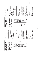
ACCESSORIES & PACKING MATERIALS
********************************
1-418-548-11
REMOTE COMMANDER (RM-SX10) (NX1)
1-418-549-11
REMOTE COMMANDER (RM-SX15) (NX3AV)
1-501-374-11
ANTENNA,LOOP
1-501-594-11
ANTENNA (FM) (AEP,UK)
1-501-659-41
ANTENNA (FM) (US,CND,E,AU,JE)
1-769-306-11
CORD,SPEAKER (1.5m) (FOR SS-NX1)
1-769-433-11
CORD,SPEAKER (1m) (FOR SS-RC100)
1-769-433-21
CORD,SPEAKER (2.5m) (FOR SS-RC100)
3-867-106-11
MANUAL,INSTRUCTION (ENGLISH)
(NX1:US,CND,AEP,UK,CIS,MY,SP,JE)
3-867-106-21
MANUAL,INSTRUCTION (FRENCH,SPANISH)
(NX1:CND,AEP,MY,SP)
3-867-106-31
MANUAL,INSTRUCTION (GERMAN) (NX1:AEP,G)
3-867-106-41
MANUAL,INSTRUCTION
(DUTCH,ITALIAN,PORTUGUESE) (NX1:AEP)
3-867-106-51
MANUAL,INSTRUCTION
(DANISH,FINISH,SWEDISH) (NX1:AED)
3-867-106-61
MANUAL,INSTRUCTION (POLISH,RUSSIAN)
(NX1:CIS)
3-867-106-71
MANUAL,INSTRUCTION (CHINESE) (NX1:MY,SP)
3-867-106-81
MANUAL,INSTRUCTION (KORIAN) (NX1:KR,JE)
3-867-106-91
MANUAL,INSTRUCTION (PORTUGUESE)
(NX1:JE)
3-867-107-11
MANUAL,INSTRUCTION (ENGLISH)
(NX3:US,CND,AEP,UK,CIS,MY,SP,AUS)
9-928-979-11
MHC-NX1/NX3AV
HCD-NX1/HCR-NX3
US Model
Canadian Model
AEP Model
UK Model
E Model
MHC-NX1/NX3AV
Tourist Model
MHC-NX1
Australian Model
MHC-NX3AV
COMPONENT MODEL NAME FOR
MHC-NX1/NX3AV
HCD-NX1 is composed of STR-NX1 and HTC-NX1.
HCR-NX3 is composed of STR-NX3 and HTC-NX1.
PARTS LIST
MHC-NX1
MHC-NX3AV
TUNER,AMPLIFIER
STR-NX1
STR-NX3
CD PLAYER ,TAPE DECK
HTC-NX1
FRONT SPEAKER SYSTEM
SS-NX1
CENTER/REAR
SS-RC100
SPEAKER SYSTEM
3-867-107-21
MANUAL,INSTRUCTION (FRENCH,SPANISH)
(NX3:CND,AEP,MY,SP)
3-867-107-31
MANUAL,INSTRUCTION (GERMAN) (NX3:AEP,G)
3-867-107-41
MANUAL,INSTRUCTION
(DUTCH,ITALIAN,PORTUGUESE) (NX3:AEP)
3-867-107-51
MANUAL,INSTRUCTION
(DANISH,FINISH,SWEDISH) (NX3:AED)
3-867-107-61
MANUAL,INSTRUCTION (POLISH,RUSSIAN)
(NX1:CIS)
3-867-107-71
MANUAL,INSTRUCTION (CHINESE) (NX3:MY,SP)
3-867-107-81
MANUAL,INSTRUCTION (KORIAN) (NX3:KR)
3-867-339-11
MANUAL,INSTRUCTION (CZECH) (NX3,AED)
3-867-339-21
MANUAL,INSTRUCTION (HUNGARIAN)
(NX3,AED)
3-867-339-31
MANUAL,INSTRUCTION (GREEK) (NX3,AED)
3-867-339-41
MANUAL,INSTRUCTION (TURKISH) (NX3,AED)
3-867-340-11
MANUAL,INSTRUCTION (CZECH) (NX3,AED)
3-867-340-21
MANUAL,INSTRUCTION (HUNGARIAN)
(NX3,AED)
3-867-340-31
MANUAL,INSTRUCTION (GREEK) (NX3,AED)
3-867-340-41
MANUAL,INSTRUCTION (TURKISH) (NX3,AED)
3-867-790-11
MANUAL,INSTRUCTION (ENGLISH,FRENCH,
GERMAN,SWEDISH,RUSSIAN) (SS-NX1)
3-867-936-11
MANUAL,INSTRUCTION (THAI) (NX1:TH)
4-210-254-01
CUSHION (FOOT) (FOR SS-NX1)
4-981-643-21
COVER,BATTERY (FOR RM-SX10/SX15)
Ref. No.
Part No.
Description
Remark
Ref. No.
Part No.
Description
Remark
• Abbreviation
AED : North European
AUS :
Australian
CND : Canadian
G :
German
JE :
Tourist
KR :
Korean
MY :
Malaysia
SP :
Singapore
TH : Thai