Sony MHC-NX1 Service Manual - Page 57
Mechanical Adjustments, Tape Deck Deck - belt
 |
View all Sony MHC-NX1 manuals
Add to My Manuals
Save this manual to your list of manuals |
Page 57 highlights
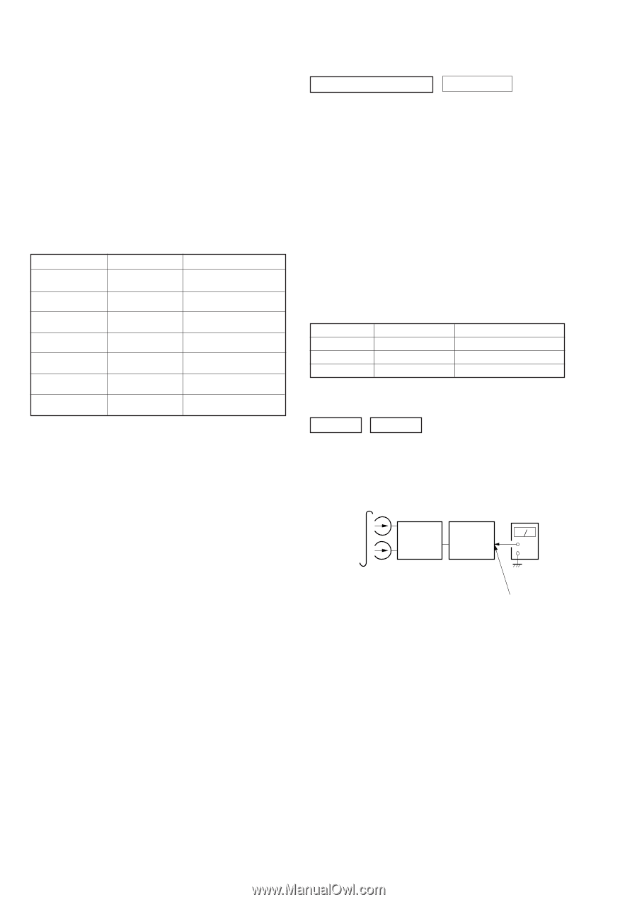
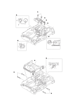
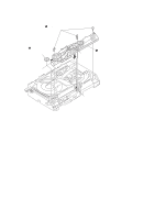
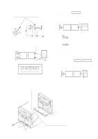
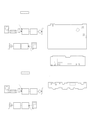
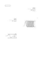
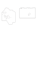
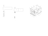
SECTION 5 MECHANICAL ADJUSTMENTS Precaution 1. Clean the following parts with a denatured alcohol-moistened swab: record/playback heads pinch rollers erase head rubber belts capstan idlers 2. Demagnetize the record/playback head with a head demagne- tizer. 3. Do not use a magnetized screwdriver for the adjustments. 4. After the adjustments, apply suitable locking compound to the parts adjusted. 5. The adjustments should be performed with the rated power sup- ply voltage unless otherwise noted. Torque Measurement Mode Torque meter FWD FWD back tension REV REV back tension FF/REW CQ-102C CQ-102C CQ-102RC CQ-102RC CQ-201B FWD tension CQ-403A REV tension CQ-403R Meter reading 31 to 71 g • cm (0.43 - 0.98 oz • inch) 2 to 6 g • cm (0.03 - 0.08 oz • inch) 31 to 71 g • cm (0.43 - 0.98 oz • inch) 2 to 6 g • cm (0.03 - 0.08 oz • inch) 71 to 143 g • cm (0.99 - 1.99 oz • inch) 100 g or more (3.53 oz or more) 100 g or more (3.53 oz or more) SECTION 6 ELECTRICAL ADJUSTMENTS TAPE DECK SECTION 0 dB=0.775 V 1. Demagnetize the record/playback head with a head demagnetizer. 2. Do not use a magnetized screwdriver for the adjustments. 3. After the adjustments, apply suitable locking compound to the parts adjust. 4. The adjustments should be performed with the rated power supply voltage unless otherwise noted. 5. The adjustments should be performed in the order given in this service manual. (As a general rule, playback circuit adjustment should be completed before performing recording circuit adjustment.) 6. The adjustments should be performed for both L-CH and RCH. 7. Switches and controls should be set as follows unless otherwise specified. 8. Set to the DOLBY NR OFF. 9. Set to the test mode. (See page 13) • Test Tape Tape P-4-A100 WS-48B P-4-L300 Signal 10 kHz, -10 dB 3 kHz, 0 dB 315 Hz, 0 dB Used for Azimuth Adjustment Tape Speed Adjustment Level Adjustment Record/Playback Head Azimuth Adjustment DECK A DECK B Note: Perform this adjustments for both decks Procedure: 1. Mode: Playback test tape P-4-A100 (10 kHz, -10 dB) set PFJ-1 or STR-NX1/ NX3 level meter + - AUDIO OUT jack 14
-
 1
1 -
2
-
3
-
4
-
5
-
6
-
7
-
8
-
9
-
10
-
11
-
12
-
13
-
14
-
15
-
16
-
17
-
18
-
19
-
20
-
21
-
22
-
23
-
24
-
25
-
26
-
27
-
28
-
29
-
30
-
31
-
32
-
33
-
34
-
35
-
36
-
37
-
38
-
39
-
40
-
41
-
42
-
43
-
44
-
45
-
46
-
47
-
48
-
49
-
50
-
51
-
 52
52 -
 53
53 -
 54
54 -
 55
55 -
 56
56 -
 57
57 -
 58
58 -
 59
59 -
 60
60 -
 61
61 -
 62
62 -
63
-
64
-
65
-
66
-
67
-
68
-
69
-
70
-
71
-
72
-
73
-
74
-
75
-
76
-
77
-
78
-
79
-
80
-
81
-
82
-
83
-
84
-
85
-
86
-
87
-
88
-
89
-
90
-
91
-
92
-
93
-
94
-
95
-
96
-
97
 |
 |