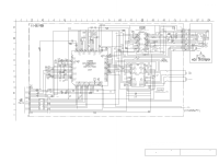
Sony MHC-NX1 Service Manual - Page 68
Schematic, Diagram, Audio Board
 |
View all Sony MHC-NX1 manuals
Add to My Manuals
Save this manual to your list of manuals |
Page 68 highlights
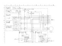
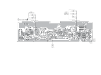
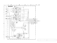
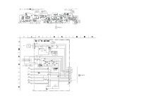
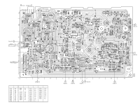
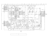
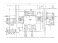
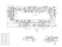
7-7. SCHEMATIC DIAGRAM - AUDIO Board - • See page 33 for IC Block Diagram. (PLAYBACK) PB EQ AMP (DECK A) PB EQ AMP (DECK B) PB LEVEL (L) (DECK A) PB LEVEL (R) (DECK A) PB LEVEL (L) (DECK B) PB LEVEL (R) (DECK B) SWITCHING NC A +7.5V APB-LCH APB-RCH AGND BPB-LCH BPB-RCH A -7.5V D (Page 28) -VBIAS (-7.5V) +VBIAS (+7.5V) B-REC-RCH B-REC-LCH TC-HEAD-GND HTC-NX1 REC BIAS (R) (DECK B) REC BIAS (L) (DECK B) BIAS OSC REC BIAS -6.8 25 25 • Voltages are dc with respect to ground under no-signal conditions. no mark : TAPE PLAYBACK ( ) : RECORD The components identified by mark 0 or dotted line with mark 0 are critical for safety. Replace only with part number specified. Les composants identifiés par une marque 0 sont critiques pour la sécurité. Ne les remplacer que par une pièce portant le numéro spécifié.
-
 1
1 -
2
-
3
-
4
-
5
-
6
-
7
-
8
-
9
-
10
-
11
-
12
-
13
-
14
-
15
-
16
-
17
-
18
-
19
-
20
-
21
-
22
-
23
-
24
-
25
-
26
-
27
-
28
-
29
-
30
-
31
-
32
-
33
-
34
-
35
-
36
-
37
-
38
-
39
-
40
-
41
-
42
-
43
-
44
-
45
-
46
-
47
-
48
-
49
-
50
-
51
-
52
-
53
-
54
-
55
-
56
-
57
-
58
-
59
-
60
-
61
-
62
-
 63
63 -
 64
64 -
 65
65 -
 66
66 -
 67
67 -
 68
68 -
 69
69 -
 70
70 -
 71
71 -
 72
72 -
 73
73 -
74
-
75
-
76
-
77
-
78
-
79
-
80
-
81
-
82
-
83
-
84
-
85
-
86
-
87
-
88
-
89
-
90
-
91
-
92
-
93
-
94
-
95
-
96
-
97
 |
 |
