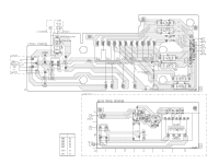
Sony MHC-NX1 Service Manual - Page 26
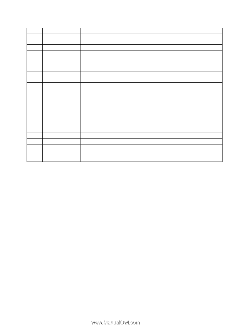
Pin No., Pin Name, Description, m - specs
 |
View all Sony MHC-NX1 manuals
Add to My Manuals
Save this manual to your list of manuals |
Page 26 highlights
Pin No. Pin Name I/O Description 87 LED 5.1CH O LED drive signal output of the DVD 5.1CH indicator (D632) "H": LED on (Used for the STR-NX3 only) 88 LED GROOVE O LED drive signal output of the GROOVE indicator (D631) "H": LED on 89 BPF 1 I Spectrum analyzer drive (low frequency) signal input from the spectrum analyzer band-pass filter (IC401) (for 100 Hz) 90 BPF 2 I Spectrum analyzer drive (low and middle frequency) signal input from the spectrum analyzer band-pass filter (IC401) (for 400 Hz) 91 BPF 3 I Spectrum analyzer drive (middle and high frequency) signal input from the spectrum analyzer band-pass filter (IC401) (for 2 kHz) 92 BPF 4 I Spectrum analyzer drive (high frequency) signal input from the spectrum analyzer band-pass filter (IC401) (for 6 kHz) Key input terminal (A/D input) 93 KEY1 I S615 to S617, S619 to S624 (TUNER BAND, STEREO/MONO, TUNER MEMORY, GROOVE, + M, - m, ENTER, DVD 5.1CH, PRO LOGIC) keys input (S623 DVD 5.1CH, S624 PRO LOGIC keys: used for the STR-NX3 only) Key input terminal (A/D input) 94 KEY0 I S601 to S614 (I/1, DISPLAY, POWER SAVE/DEMO (STANDBY), VIDEO/DVD, MD, TAPE, CD, TUNER, DSB, DBFB, PLAY MODE, REPEAT, EDIT, FILE SELECT) keys input 95 MODEL-IN I Destination setting terminal 96 AVSS - Ground terminal (for A/D conversion) 97 SPEC-IN I Setting terminal for the version 98 VREF I Reference voltage (+5V) input terminal (for A/D conversion) 99 AVCC - Power supply terminal (+5V) (for A/D conversion) 100 POWER O Power on/off control signal output terminal "L": standby mode, "H": power on 25
-
 1
1 -
2
-
3
-
4
-
5
-
6
-
7
-
8
-
9
-
10
-
11
-
12
-
13
-
14
-
15
-
16
-
17
-
18
-
19
-
20
-
 21
21 -
 22
22 -
 23
23 -
 24
24 -
 25
25 -
 26
26 -
 27
27 -
 28
28 -
 29
29 -
 30
30 -
 31
31 -
32
-
33
-
34
-
35
-
36
-
37
-
38
-
39
-
40
-
41
-
42
-
43
-
44
-
45
-
46
-
47
-
48
-
49
-
50
-
51
-
52
-
53
-
54
-
55
-
56
-
57
-
58
-
59
-
60
-
61
-
62
-
63
-
64
-
65
-
66
-
67
-
68
-
69
-
70
-
71
-
72
-
73
-
74
-
75
-
76
-
77
-
78
-
79
-
80
-
81
-
82
-
83
-
84
-
85
-
86
-
87
-
88
-
89
-
90
-
91
-
92
-
93
-
94
-
95
-
96
-
97
 |
 |