Sony MHC-NX1 Service Manual - Page 58
DECK B, Deck A is RV311 L-CH and RV411 R-CH, Deck B is RV301
 |
View all Sony MHC-NX1 manuals
Add to My Manuals
Save this manual to your list of manuals |
Page 58 highlights
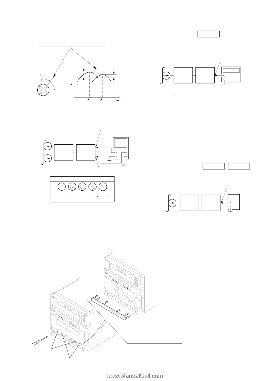
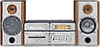
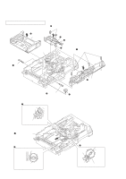
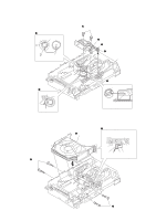
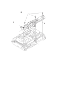
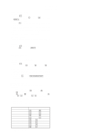
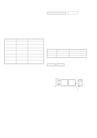
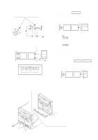
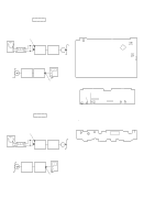
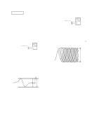
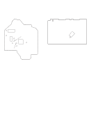
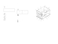
2. Turn the adjustment screw and check output peaks. If the peaks do not match for L-CH and R-CH, turn the adjustment screw so that outputs match within 1dB of peak. L-CH peak within 1dB Output level within 1dB Tape Speed Adjustment DECK B • Execute only if connected to the STR-NX1/NX3 Mode: Playback test tape WS-48B (3 kHz, 0 dB) AUDIO OUT jack frequency counter set STR-NX1/ + NX3 - Screw position R-CH peak L-CH R-CH peak peak Screw position 3. Mode: Playback test tape P-4-A100 (10 kHz, -10 dB) L-CH set AUDIO OUT (L) jack oscilloscope PFJ-1 or L-CH VH STR-NX1/ NX3 R-CH R-CH AUDIO OUT (R) jack waveform of oscilloscope in phase 45° 90° 135° 180° good wrong 4. Repeat step 1 to 3 in playback (REV) mode. 5. After the adjustments, apply suitable locking compound to the pats adjusted. Adjustment Location: Playback Head (Deck A). Record/Playback/Earth Head (Deck B). 1. Insert the WS-48B into the deck B. 2. Press the G (DECK B) button. 3. Press the [HI-DUB] button in playback mode. Then at HIGH speed mode. 4. Adjust RV1001 on the LEAF SW board do that frequency counter reads 6,000 ± 180 Hz. 5. Press the [HI-DUB] button. Then back to NORMAL speed mode. 6. Adjust RV1002 on the LEAF SW board so that frequency counter reads 3,000 ± 90 Hz. Adjustment Location: LEAF SW board Sample value of Wow and Flutter: 0.3% or less W.RMS (JIS) (WS-48B) Playback level Adjustment DECK A Procedure: Mode: Playback DECK B test tape P-4-L300 (315 Hz, 0 dB) set AUDIO OUT jack level meter PFJ-1 or STR-NX1/ NX3 + - Deck A is RV311 (L-CH) and RV411 (R-CH), Deck B is RV301 (L-CH) and RV401 (R-CH) so that adjustment within specified value as follows. Specified Value: AUDIO OUT jack PB level: 301.5 to 338.3 mV (-8.2 to -7.2 dB) level difference between the channels: within ± 0.5 dB Adjustment Location: AUDIO board Open the cassette holder and unhock six claws of the sub panel (TC2) with tweezers or something, then remove the sub panel (TC2). forward reverse 15
-
 1
1 -
2
-
3
-
4
-
5
-
6
-
7
-
8
-
9
-
10
-
11
-
12
-
13
-
14
-
15
-
16
-
17
-
18
-
19
-
20
-
21
-
22
-
23
-
24
-
25
-
26
-
27
-
28
-
29
-
30
-
31
-
32
-
33
-
34
-
35
-
36
-
37
-
38
-
39
-
40
-
41
-
42
-
43
-
44
-
45
-
46
-
47
-
48
-
49
-
50
-
51
-
52
-
 53
53 -
 54
54 -
 55
55 -
 56
56 -
 57
57 -
 58
58 -
 59
59 -
 60
60 -
 61
61 -
 62
62 -
 63
63 -
64
-
65
-
66
-
67
-
68
-
69
-
70
-
71
-
72
-
73
-
74
-
75
-
76
-
77
-
78
-
79
-
80
-
81
-
82
-
83
-
84
-
85
-
86
-
87
-
88
-
89
-
90
-
91
-
92
-
93
-
94
-
95
-
96
-
97
 |
 |