Sony MHC-NX1 Service Manual - Page 78
LOD-POS pin, CD elevator up/down motor M701 control
 |
View all Sony MHC-NX1 manuals
Add to My Manuals
Save this manual to your list of manuals |
Page 78 highlights
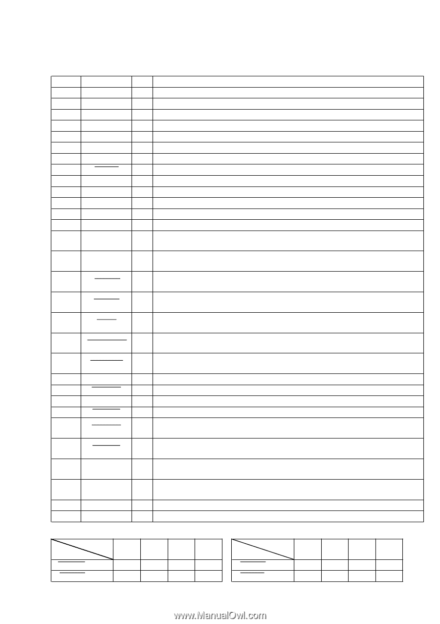
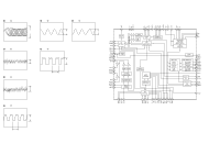
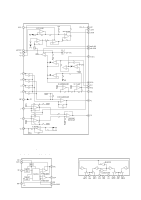
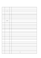
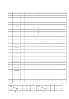
Pin No. Pin Name I/O Description 42 LED A CDPL O LED drive signal output of the G (CD) indicator (D211) "L": LED on 43 LED A RECP O LED drive signal output terminal Not used (open) 44 LED R RECP O LED drive signal output of the REC PAUSE/START indicator (D217) "H": LED on 45 LED SYNC O LED drive signal output of the CD SYNC indicator (D216) "H": LED on 46 XWR I Not used (fixed at "H") 47 SOFT MODE1 I Destination setting terminal (normally: fixed at "L") 48 SOFT MODE0 I Destination setting terminal (normally: fixed at "L") 49 CD ADJ I Setting terminal for the CD test mode Normally: fixed at "H" ("L": test mode) 50 LED TCB R O LED drive signal output of the g (DECK B) indicator (D205) "L": LED on 51 LED TCB F O LED drive signal output of the G (DECK B) indicator (D207) "L": LED on 52 LED TCA R O LED drive signal output of the g (DECK A) indicator (D206) "L": LED on 53 LED TCA F O LED drive signal output of the G (DECK A) indicator (D208) "L": LED on 54 AMUTE O Analog line muting on/off control signal output terminal "H": line muting on Not used (open) 55 CD-POWER O Power on/off control signal output of the CD mechanism deck section "L": standby mode, "H": power on 56 PRTC SW I Detection input from the CD tray door open/close detect switch (S702) "L": when CD lid is open, "H": when CD lid is close 57 INIT SW I Detection input from the INIT detection switch (S705) on the CD mechanism block "L": when elevator down to bottom, others: "H" 58 OUT SW I Detection input from the tray open/close detect switch (S708) on the CD mechanism block "L": when tray is open, "H": when tray is close 59 IN SW I Detection input from the tray open/close detect switch (S704) on the CD mechanism block "L": when tray is close, "H": when tray is open 60 MIDOUT SW I Detection input from the mid out detect switch (S701) on the CD mechanism block "L": when tray is going to open or close 61 MIDIN SW I Detection input from the mid in detect switch (S703) on the CD mechanism block "L": when sub tray move between tray and stocker 62 VCC - Power supply terminal (+5V) 63 LOD-NEG O CD loading motor (M702) control signal output to the motor driver IC (IC702) "L" active *1 64 VSS - Ground terminal 65 LOD-POS O CD loading motor (M702) control signal output to the motor driver IC (IC702) "L" active *1 66 CLP-NEG O CD elevator up/down motor (M701) control signal output to the motor driver IC (IC701) "L" active *2 67 CLP-POS O CD elevator up/down motor (M701) control signal output to the motor driver IC (IC701) "L" active *2 68 to 70 ENC2, ENC1,ENC0 I Detection input from the disc tray address detect rotary encoder (S707) on the CD mechanism block 71 TC-RELAY O Recording/playback select signal output to the REC/PB switch (IC602) "L": playback, "H": recording 72 B-TRG O Deck-B side trigger plunger drive signal output terminal "H": plunger on 73 A-TRG O Deck-A side trigger plunger drive signal output terminal "H": plunger on *1 CD loading motor (M702) control Terminal MMooddee Loading Eject Stop Brake LOD-NEG (pin yd ) "L" "H" "H" "L" LOD-POS (pin yg ) "H" "L" "H" "L" *2 CD elevator up/down motor (M701) control Terminal MMooddee Elevator Elevator Stop Up Down CLP-NEG (pin yh ) "L" "H" "H" CLP-POS (pin yj ) "H" "L" "H" Brake "L" "L" 35
-
 1
1 -
2
-
3
-
4
-
5
-
6
-
7
-
8
-
9
-
10
-
11
-
12
-
13
-
14
-
15
-
16
-
17
-
18
-
19
-
20
-
21
-
22
-
23
-
24
-
25
-
26
-
27
-
28
-
29
-
30
-
31
-
32
-
33
-
34
-
35
-
36
-
37
-
38
-
39
-
40
-
41
-
42
-
43
-
44
-
45
-
46
-
47
-
48
-
49
-
50
-
51
-
52
-
53
-
54
-
55
-
56
-
57
-
58
-
59
-
60
-
61
-
62
-
63
-
64
-
65
-
66
-
67
-
68
-
69
-
70
-
71
-
72
-
 73
73 -
 74
74 -
 75
75 -
 76
76 -
 77
77 -
 78
78 -
 79
79 -
 80
80 -
 81
81 -
 82
82 -
 83
83 -
84
-
85
-
86
-
87
-
88
-
89
-
90
-
91
-
92
-
93
-
94
-
95
-
96
-
97
 |
 |