Sony MHC-NX1 Service Manual - Page 7
Disassembly, Front, Panel, Ass'y
 |
View all Sony MHC-NX1 manuals
Add to My Manuals
Save this manual to your list of manuals |
Page 7 highlights
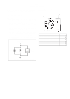
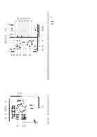
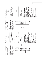
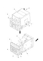
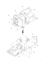
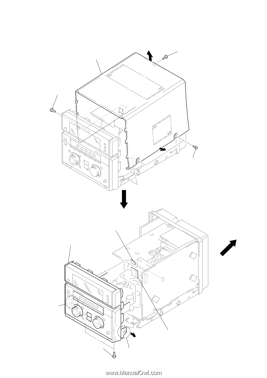
SECTION 3 DISASSEMBLY Note: Follow the disassembly procedure in the numerical order given. CASE 3 case 1 two screws (case 3 TP2) 2 screw (BVTP3 × 10) FRONT PANEL ASS'Y 4 front panel ass'y 1 flat wire (CN132) 1 two screws (case 3 TP2) 3 claw 2 two screws (BVTT3 × 6) 3 claw 1 flat wire (CN131) 6
-
 1
1 -
 2
2 -
 3
3 -
 4
4 -
 5
5 -
 6
6 -
 7
7 -
 8
8 -
 9
9 -
 10
10 -
 11
11 -
 12
12 -
13
-
14
-
15
-
16
-
17
-
18
-
19
-
20
-
21
-
22
-
23
-
24
-
25
-
26
-
27
-
28
-
29
-
30
-
31
-
32
-
33
-
34
-
35
-
36
-
37
-
38
-
39
-
40
-
41
-
42
-
43
-
44
-
45
-
46
-
47
-
48
-
49
-
50
-
51
-
52
-
53
-
54
-
55
-
56
-
57
-
58
-
59
-
60
-
61
-
62
-
63
-
64
-
65
-
66
-
67
-
68
-
69
-
70
-
71
-
72
-
73
-
74
-
75
-
76
-
77
-
78
-
79
-
80
-
81
-
82
-
83
-
84
-
85
-
86
-
87
-
88
-
89
-
90
-
91
-
92
-
93
-
94
-
95
-
96
-
97
 |
 |
6
CASE
FRONT
PANEL
ASS’Y
Note:
Follow the disassembly procedure in the numerical order given.
SECTION
3
DISASSEMBLY
3
case
1
two screws
(case 3 TP2)
2
screw
(BVTP3
×
10)
1
two screws
(case 3 TP2)
2
two screws
(BVTT3
×
6)
3
claw
3
claw
4
front panel ass’y
1
flat wire
(CN132)
1
flat wire
(CN131)