Sony MHC-NX1 Service Manual - Page 60
S-CURVE, CHECK, CD LEVEL, Connect oscilloscope to TP FEO.
 |
View all Sony MHC-NX1 manuals
Add to My Manuals
Save this manual to your list of manuals |
Page 60 highlights
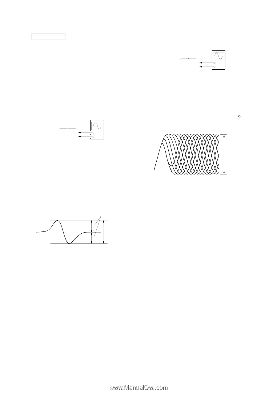
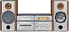
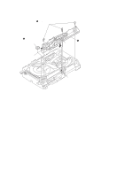
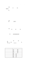
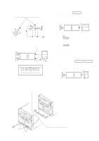
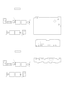
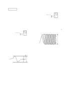
CD SECTION Note: 1. CD Block is basically designed to operate without adjustment. There- fore, check each item in order given. 2. Use YEDS-18 disc (3-702-101-01) unless otherwise indicated. 3. Use an oscilloscope with more than 10 MΩ impedance. 4. Clean the object lens by an applicator with neutral detergent when the signal level is low than specified value with the following checks. 5. Use the following extension cables and relay connector. • Extension cable (19P) (Part No. J-2501-011-B) Relay connector (Part No. J-2501-167-A) (BD board CN101 to MAIN board CN111) • Extension cable (17P) (with connector) (Part No. J-2501-167-A) (CONNECTOR board CN701 to MAIN board CN301) 1. S-CURVE CHECK BD board TP (FEO) TP (VC) oscilloscope + - Procedure: 1. Connect oscilloscope to TP (FEO). 2. Connect between TP (FEO) and TP (VC) by lead wire. 3. Connect between TP (AGCCON) and TP (GND) by lead wire. 4. Turn the power ON. 5. Load a disc (YEDS-18) and turn the power ON again and ac- tuate the focus search. (Actuate the focus search when disc tray is moving in and out) 6. Check the oscilloscope waveform (S-curve) is symmetrical between A and B. And confirm peak to peak level within 2.4±0.7 Vp-p. S-curve waveform symmetry 2. RF LEVEL CHECK BD board TP (RF) TP (VC) oscilloscope + - Procedure: 1. Connect oscilloscope to TP (RF). As TP (RF) and TP (VC) are located at the edge of board, clip them together with the board using alligator clips. 2. Turn the power ON. 3. Load a disc (YEDS-18) and playback. 4. Confirm that oscilloscope waveform is clear and check RF signal level is correct or not. Note: Clear RF signal waveform means that the shape " " can be clearly distinguished at the center of the waveform. RF signal waveform VOLT/DIV: 200 mV TIME/DIV: 500 ns level: 1.2 ± 0.2 Vp-p A within 2.4 ± 0.7 Vp-p B 7. After check, remove the lead wire connected in step 2. Note: • Try to measure several times to make sure than the ratio of A : B or B : A is more than 10 : 7. • Take sweep time as long as possible and light up the brightness to obtain best waveform. 17
-
 1
1 -
2
-
3
-
4
-
5
-
6
-
7
-
8
-
9
-
10
-
11
-
12
-
13
-
14
-
15
-
16
-
17
-
18
-
19
-
20
-
21
-
22
-
23
-
24
-
25
-
26
-
27
-
28
-
29
-
30
-
31
-
32
-
33
-
34
-
35
-
36
-
37
-
38
-
39
-
40
-
41
-
42
-
43
-
44
-
45
-
46
-
47
-
48
-
49
-
50
-
51
-
52
-
53
-
54
-
 55
55 -
 56
56 -
 57
57 -
 58
58 -
 59
59 -
 60
60 -
 61
61 -
 62
62 -
 63
63 -
 64
64 -
 65
65 -
66
-
67
-
68
-
69
-
70
-
71
-
72
-
73
-
74
-
75
-
76
-
77
-
78
-
79
-
80
-
81
-
82
-
83
-
84
-
85
-
86
-
87
-
88
-
89
-
90
-
91
-
92
-
93
-
94
-
95
-
96
-
97
 |
 |