Sony MZ-R50 Service Manual - Page 20
Disassembly - battery
 |
View all Sony MZ-R50 manuals
Add to My Manuals
Save this manual to your list of manuals |
Page 20 highlights
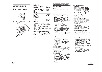
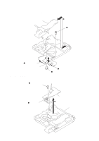
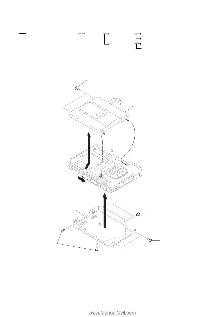
SECTION 3 DISASSEMBLY r The equipment can be removed using the following procedure. Set Upper panel assy, Bottom panel assy Main board Mechanism deck Battery case assy Note : Follow the disassembly procedure in the numerical order given. 3-1. UPPER PANEL ASSY, BOTTOM PANEL ASSY REMOVAL Optical pick-up assy, REC board CLV board Power board, Switch board SWITCH UNIT (with JOG DIAL) 1 Screws (M1.4 precision pan) Upper panel assy 3 2 Knob (Open) Bottom panel assy 7 6 Screw (M1.4 precision pan) 4 Screws (M1.4 precision pan) 5 Screws (M1.4 precision pan) - 20 -
-
 1
1 -
2
-
3
-
4
-
5
-
6
-
7
-
8
-
9
-
10
-
11
-
12
-
13
-
14
-
 15
15 -
 16
16 -
 17
17 -
 18
18 -
 19
19 -
 20
20 -
 21
21 -
 22
22 -
 23
23 -
 24
24 -
 25
25 -
26
-
27
-
28
-
29
-
30
-
31
-
32
-
33
-
34
-
35
-
36
-
37
-
38
-
39
-
40
-
41
-
42
-
43
-
44
-
45
-
46
-
47
-
48
-
49
-
50
-
51
-
52
-
53
-
54
-
55
-
56
 |
 |
– 20 –
SECTION 3
DISASSEMBLY
Note :
Follow the disassembly procedure in the numerical order given.
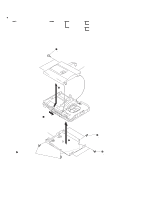
3-1. UPPER PANEL ASSY, BOTTOM PANEL ASSY REMOVAL
r
The equipment can be removed using the following procedure.
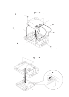
Set
Upper panel assy, Bottom panel assy
Main board
Mechanism deck
SWITCH UNIT (with JOG DIAL)
Power board, Switch board
CLV board
Optical pick-up assy, REC board
Battery case assy
7
3
1
Screws
(M1.4 precision pan)
Upper panel assy
2
Knob (Open)
4
Screws
(M1.4 precision pan)
6
Screw
(M1.4 precision pan)
5
Screws
(M1.4 precision pan)
Bottom panel assy