Sony MZ-R50 Service Manual - Page 31
Adjustments
 |
View all Sony MZ-R50 manuals
Add to My Manuals
Save this manual to your list of manuals |
Page 31 highlights
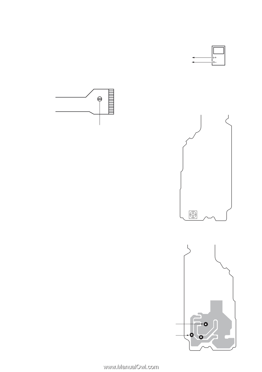
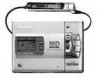
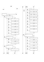
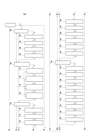
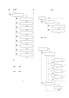
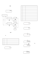
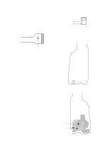
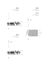
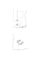
SECTION 5 ADJUSTMENTS 5-1. Precautions for Laser Diode Emission Check When checking the emission of the laser diode during adjustments, never view directly downwards as this may lead to blindness. 5-2. Precautions for Using Optical Pickup (KMS-280A) As the laser diode inside the optical pickup damages by static electricity easily, solder the laser tap of the flexible board when handling. Also take the necessary measures to prevent damages by static electricity. Handle the flexible board with care as it breaks easily 5-4. DD 2.8V Adjustment Connection : POWER board TP8507 (+2.8V) TP8505 (AGND) Digital voltmeter Adjusting Method : 1. Connect the digital voltmeter to test point TP8507 (+2.8V) and TP8505 (AGND) on power board. 2. Adjust the RV801 for 2.8V reading on the digital voltmeter. Connection point and adjustment location : POWER board [POWER BOARD] (SIDE A) Laser tap Optical Pickup flexible board 5-3. Precautions for Adjustment 1) Perform all adjustments in the order given in the test mode. After adjusting, exit the test mode. 2) Use the following tools and measuring instruments. • CD test disc TDYS-1 (Parts Code : 4-963-646-01) • Recorded MO disc PTDM-1 (Parts Code : J-2501-054-A) • Laser power meter LPM-1 (Parts Code : J-2501-046-A) • Oscilloscope (Frequency band above 40MHz. Perform the calibration of probe first before measuring.) • Digital voltmeter 3) Unless specified othewise, supply DC 6V from the DC IN 6V jack. 4) Swtich, knob positions Hold switch OFF AVLS switch NORM RV801 [POWER BOARD] (SIDE B) TP8505 (AGND) TP8507 (+2.8V) TP8505 TP8507 TP8503 - 31 -
-
 1
1 -
2
-
3
-
4
-
5
-
6
-
7
-
8
-
9
-
10
-
11
-
12
-
13
-
14
-
15
-
16
-
17
-
18
-
19
-
20
-
21
-
22
-
23
-
24
-
25
-
 26
26 -
 27
27 -
 28
28 -
 29
29 -
 30
30 -
 31
31 -
 32
32 -
 33
33 -
 34
34 -
 35
35 -
 36
36 -
37
-
38
-
39
-
40
-
41
-
42
-
43
-
44
-
45
-
46
-
47
-
48
-
49
-
50
-
51
-
52
-
53
-
54
-
55
-
56
 |
 |