Sony MZ-R50 Service Manual - Page 32
Laser Power Check, 6. MO Traverse Adjustment - specifications
 |
View all Sony MZ-R50 manuals
Add to My Manuals
Save this manual to your list of manuals |
Page 32 highlights
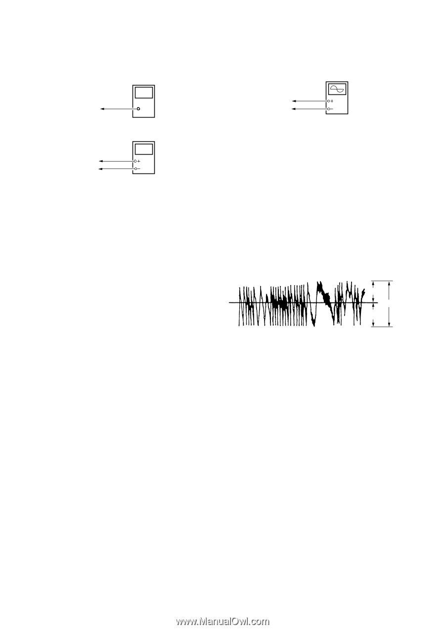
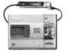
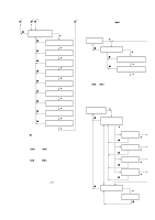
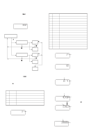
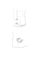
5-5. Laser Power Check Connection : Laser power meter Optical pickup objective lens MAIN board AP5117 (VCC) AP574 (LDIO) Digital voltmeter Adjusting Method : 1. Set the servo mode of the test mode (Mode : 000). 2. Press the " key, and set the laser power adjustment mode (Mode : 020) using the volume + and - keys. 3. Press the = key and move the optical pickup to the inner most circumference. 4. Open the cover and set the laser power meter on the objective lens of the optical pickup. 5. Press the " key, and set the laser MO read adjustment mode (Mode : 021). 6. Check that the laser power meter reading is 0.85 ±0.085mW. 7. Check that the voltage between AP574 (LDIO) and AP5117 (VCC) at this time is below 44mV. 8. Press the " key, and set the laser MO write adjustment mode (Mode : 022). 9. Check that the laser power meter reading is 6.8 ±0.68mW. 10.Press the P key to finalize the adjustment data. 11.Check that the voltage between AP574 (LDIO) and AP5117 (VCC) at this time is below 80mV. 12.Press the p key. 13.Exit the test mode. 5-6. MO Traverse Adjustment Connection : Oscilloscope MAIN board TP5980 (TE) AP5430 (VC) Adjusting Method : 1. Set the servo mode of the test mode (Mode : 000). 2. Press the " key, and set the MO playback adjustment mode (Mode : 030) using the volume + and - keys. 3. Press the = and + keys and move the optical pickup to the center circumference. 4. Load any MO disc available on the market. 5. When the " key is pressed, the MO playback EF balance adjust- ment mode (Mode : 032) will be set after focus search ON (Mode : 031). 6. Press the P key to perform automatic adjustment, and check that the traverse waveform is symmetrical at the top and bottom. 7. Slide the recording key and set the MO recording EF balance adjustment mode (Mode : 034). 8. Press the P key to perform automatic adjustment, and check that the traverse waveform is symmetrical at the top and bottom. (Traverse Waveform) A 0V C B Specification : A = B, C >= 1.0 Vp-p 9. Check that the traverse level at this time is above 1.0Vp-p. 10.Press the p key. 11.Exit the test mode. Note : Using a recorded disc in this adjustment will erase the data. - 32 -
-
 1
1 -
2
-
3
-
4
-
5
-
6
-
7
-
8
-
9
-
10
-
11
-
12
-
13
-
14
-
15
-
16
-
17
-
18
-
19
-
20
-
21
-
22
-
23
-
24
-
25
-
26
-
 27
27 -
 28
28 -
 29
29 -
 30
30 -
 31
31 -
 32
32 -
 33
33 -
 34
34 -
 35
35 -
 36
36 -
 37
37 -
38
-
39
-
40
-
41
-
42
-
43
-
44
-
45
-
46
-
47
-
48
-
49
-
50
-
51
-
52
-
53
-
54
-
55
-
56
 |
 |