Sony MZ-R50 Service Manual - Page 25
Test Mode - power supply
 |
View all Sony MZ-R50 manuals
Add to My Manuals
Save this manual to your list of manuals |
Page 25 highlights
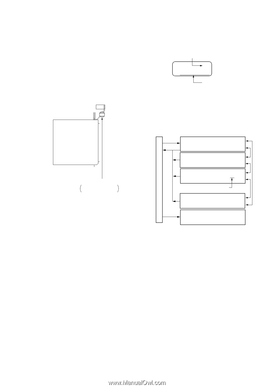
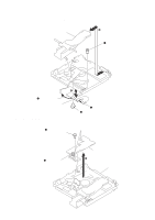
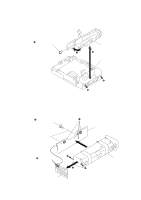
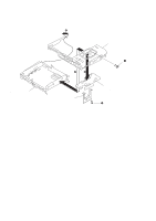
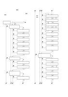
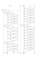
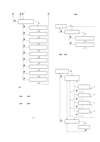
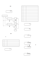
SECTION 4 TEST MODE [Outline] • The general adjustment mode of this unit performs CD and MO adjustments automatically when set. In this mode, the disc is determined if CD or MO and adjustments are automatically performed in order. If errors are detected , the faulty locations are displayed. The servo mode performs each adjustment automatically. [Setting the Test Mode] Short-circuit the soldering bridge of TAP803 (TEST) on the main board (connect Pin @§ of IC801 to the GND) and turn on the power supply. [MAIN BOARD] (SIDE B) C315 26 TAP803 (TEST) 25 [Operations When Test Mode is Set] When the test mode is set, the LCD will display as follows. Self-diagnostic display (displayed while the DISPLAY key is pressed) 00 Segment section Ver 01.00 Dot section ROM version displayed • The LCD performs the following repeatedly. ROM version displayed / all lit / all off • The display can be held and checked by pressing P key. • The self-diagnostic display appears while the DISPLAY key is pressed. [Structure of Test Mode] The test mode of this unit consists of the following five modes. Display when Test Mode is Set VOLUME +key or - key IC801 1 100 TAP803 (Test mode) Short : Test mode Open : Normal mode [Exiting the Test Mode] Turn off the power supply and open the soldering bridge of TAP803 (TEST) on the main board. + key p key = key Servo Mode Segment Section : 00 Dot Section : SERVO Audio Mode Segment Section : 00 Dot Section : AUDIO Mecha Mode Segment Section : 00 00 Dot Section : MECHA Select dial number (blinks) Power Mode Segment Section : 00 Dot Section : POWER General Adjustment Mode Segment Section : 4000 Dot Section : Assy MODE • In modes other than the general adjustment mode, the last two digits of the mode number will be displayed at the 00 section. - 25 -
-
 1
1 -
2
-
3
-
4
-
5
-
6
-
7
-
8
-
9
-
10
-
11
-
12
-
13
-
14
-
15
-
16
-
17
-
18
-
19
-
 20
20 -
 21
21 -
 22
22 -
 23
23 -
 24
24 -
 25
25 -
 26
26 -
 27
27 -
 28
28 -
 29
29 -
 30
30 -
31
-
32
-
33
-
34
-
35
-
36
-
37
-
38
-
39
-
40
-
41
-
42
-
43
-
44
-
45
-
46
-
47
-
48
-
49
-
50
-
51
-
52
-
53
-
54
-
55
-
56
 |
 |