Sony MZ-R50 Service Manual - Page 33
Low Reflection CD Traverse Adjustment, 8. CD Traverse Adjustment, 9. CD RF Level Check
 |
View all Sony MZ-R50 manuals
Add to My Manuals
Save this manual to your list of manuals |
Page 33 highlights
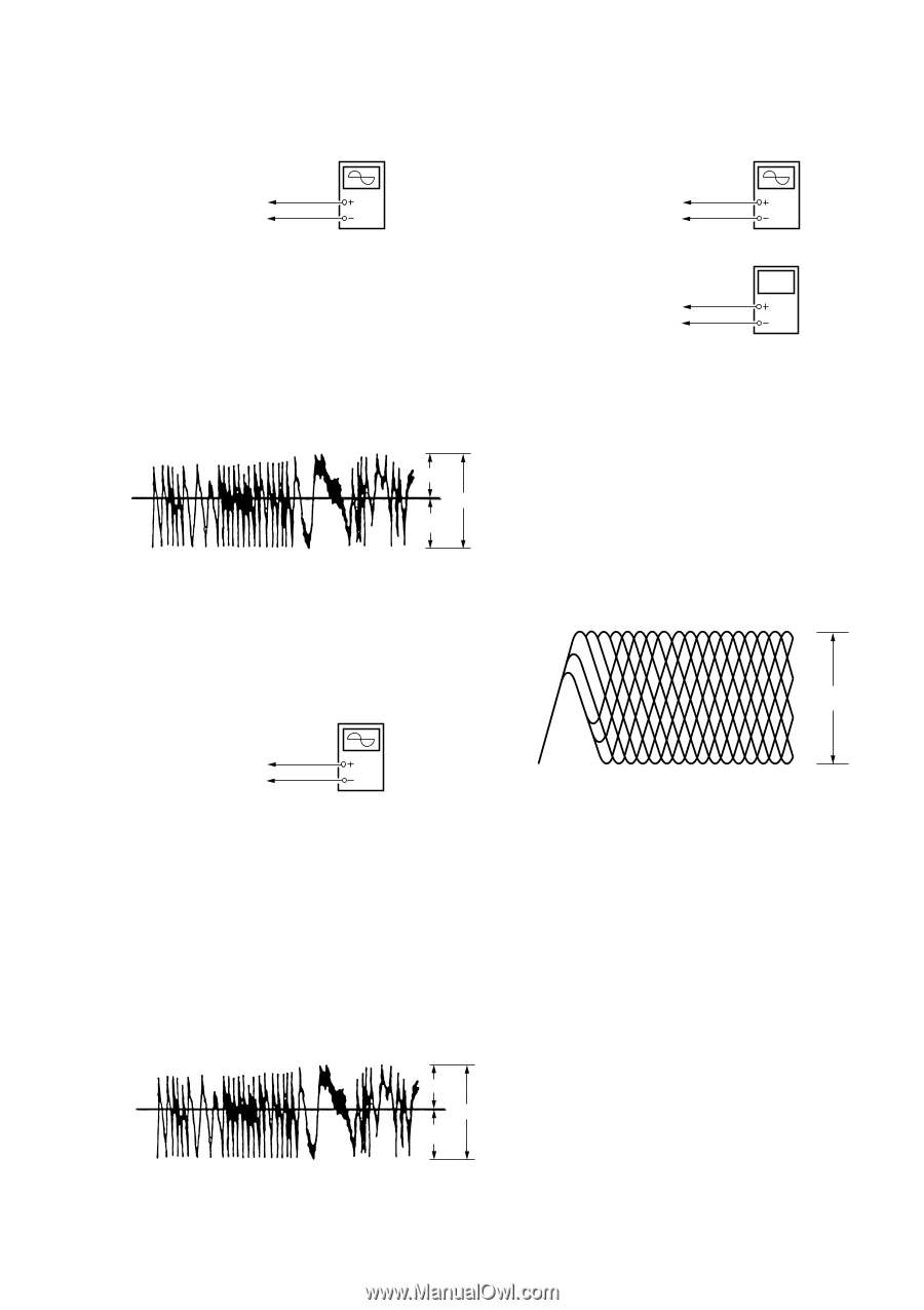
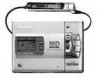
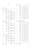
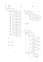
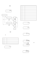
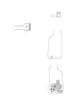
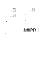
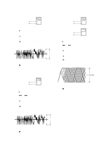
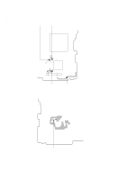
5-7. Low Reflection CD Traverse Adjustment Connection : Oscilloscope MAIN board TP5980 (TE) AP5430 (VC) Adjusting Method : 1. Set the servo mode of the test mode (Mode : 000). 2. Press the " key, and set the low reflection CD playback adjust- ment mode (Mode : 040) using the volume + and - keys. 3. Load any MO disc available on the market. 4. When the " key is pressed, the low reflection CD playback EF balance adjustment mode (Mode : 042) will be set after low reflection CD focus search ON (Mode : 041). 5. Press the P key to perform automatic adjustment, and check that the traverse waveform is symmetrical at the top and bottom. (Traverse Waveform) A 0V C B Specification : A = B, C >= 0.9Vp-p 6. Check that the traverse level at this time is above 0.9Vp-p. 7. Press the p key. 8. Exit the test mode. 5-9. CD RF Level Check Connection : MAIN board AP5500 (RF) AP5430 (VC) Oscilloscope Digital voltmeter MAIN board AP5117 (VCC) AP574 (LDIO) Adjusting Method : 1. Set the servo mode of the test mode (Mode : 000). 2. Press the " key, and set the CD playback adjustment mode (Mode : 050) using the volume + and -keys. 3. Press the = and + keys and move the optical pickup to the center circumference. 4. Load a CD test disc (TDYS-1). 5. When the " key is pressed, the CD EF balance adjustment mode (Mode : 052) will be set after CD focus search ON (Mode : 051). 6. When the " key is pressed, the ABCD level adjustment mode (Mode : 053) is set. 7. Press the P key to perform automatic adjustment, and check that the RF level is 1.1 ±0.3Vp-p. (RF waveform) 5-8. CD Traverse Adjustment Connection : Oscilloscope MAIN board TP5980 (TE) AP5430 (VC) Adjusting Method : 1. Set the servo mode of the test mode (Mode : 000). 2. Press the " key, and set the CD playback adjustment mode (Mode : 050) using the volume + and - keys. 3. Press the = and + keys and move the optical pickup to the center circumference. 4. Load a CD test disc (TDYS-1). 5. When the " key is pressed, the CD playback EF balance adjust- ment mode (Mode : 052) will be set after CD focus search ON (Mode : 051). 6. Press the P key to perform automatic adjustment, and check that the traverse waveform is symmetrical at the top and bottom. (Traverse Waveform) 1.1 - 0.3 Vp-p 8. Check that the voltage between AP574 (LDIO) and AP5117 (VCC) and at this time is below 40mV. 9. Press the p key. 10.Exit the test mode. A 0V C B Specification : A = B, C >= 1.0 Vp-p 7. Check that the traverse level at this time is above 1.0Vp-p. 8. Press the p key. 9. Exit the test mode. - 33 -
-
 1
1 -
2
-
3
-
4
-
5
-
6
-
7
-
8
-
9
-
10
-
11
-
12
-
13
-
14
-
15
-
16
-
17
-
18
-
19
-
20
-
21
-
22
-
23
-
24
-
25
-
26
-
27
-
 28
28 -
 29
29 -
 30
30 -
 31
31 -
 32
32 -
 33
33 -
 34
34 -
 35
35 -
 36
36 -
 37
37 -
 38
38 -
39
-
40
-
41
-
42
-
43
-
44
-
45
-
46
-
47
-
48
-
49
-
50
-
51
-
52
-
53
-
54
-
55
-
56
 |
 |