Sony MZ-R50 Service Manual - Page 29
Mecha Mode], Power supply Mode]
 |
View all Sony MZ-R50 manuals
Add to My Manuals
Save this manual to your list of manuals |
Page 29 highlights
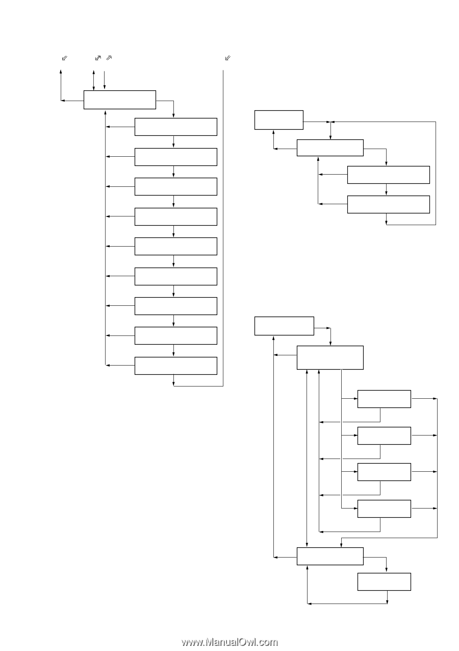
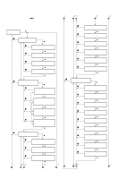
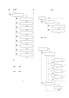
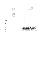
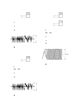
6 78 9 p key DigitaM l Mode : 150 AGC Adjustment 3 " key p key p key p key p key p key p key p key p key p key Mode : 151 MAN UP SR " key Mode : 152 MAN DOWN SR " key Mode : 153 AUTO THD3 " key Mode : 154 AUTO LMT UP SR " key Mode : 155 AUTO LMT DOWN SR " key Mode : 156 MAN THD3 " key Mode : 157 MANU LMT UP SR " key Mode : 158 MANU LMT DOWN SR " key Mode : 159 THD1 " key • When the P key is pressed at mode numbers 100, 110 to 114, the buzzer will sound. • When the VOLUME keys + and - are pressed at mode numbers 111 to 113, 123, 124, the volume of the headphone output will increase/decrease. When the = key or + key is pressed, the volume of the headphone output will become maximum/minimum. • When the VOLUME keys + and - are pressed at mode numbers 121 or 122, the recording level will increase/decrease. When the = key or + key is pressed, the recording level will become maximum/minimum. • The record LED lights up in mode numbers 121 to 124 and are off at mode numbers 110 to 114. • At mode numbers 121 to 124, the microprocessor will detect the port and automatically determine the input. • The following indicators light up with the deck sensor switches at ON. At REFLECT switch ON : the "f" indicator lights up At MEDIA switch ON : the "SHUF" indicator lights up At PROTECT switch ON : the "1" indicator lights up [Mecha Mode] • Set the test mode, press the + key, and set the mecha mode using the VOLUME + and - keys. • To set other modes, refer to "Structure of Test Mode". • Structure of Mecha Mode Mode : 200 Mecha Mode " key p key MM ode : 210 Mechanism check " key p key p key Mode : 211 EJECTM prohibited " key Mode : 212 MagnetiM c head ON " key • At mode numbers 200, 210 to 212, the optical pick up can be moved to the outer circumference or inner circumference using the = or + key. [Power supply Mode] • Set the test mode, press the + key, and set the power supply mode using the VOLUME + and - keys. • To set other modes, refer to "Structure of Test Mode". • Structure of Power Supply Mode Mode : 300 " key Power supply mode p key MM ode : 310 Power supply discrimination test " key (Automatic discrimination) Mode : 311 Ni MH p key " key VOLUME +key or - key Mode : 312 AM3 ! 2 p key " key Mode : 313 DC IN p key " key Mode : 314 EXT BATT p key " key p key Mode : 320 Charge test " key Mode : 321 Main Charge p key - 29 -
-
 1
1 -
2
-
3
-
4
-
5
-
6
-
7
-
8
-
9
-
10
-
11
-
12
-
13
-
14
-
15
-
16
-
17
-
18
-
19
-
20
-
21
-
22
-
23
-
 24
24 -
 25
25 -
 26
26 -
 27
27 -
 28
28 -
 29
29 -
 30
30 -
 31
31 -
 32
32 -
 33
33 -
 34
34 -
35
-
36
-
37
-
38
-
39
-
40
-
41
-
42
-
43
-
44
-
45
-
46
-
47
-
48
-
49
-
50
-
51
-
52
-
53
-
54
-
55
-
56
 |
 |