Sony STR-AV880 Operating Instructions - Page 18
Connection, Diagrams
 |
View all Sony STR-AV880 manuals
Add to My Manuals
Save this manual to your list of manuals |
Page 18 highlights
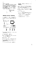
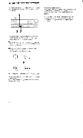
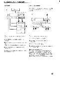
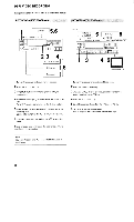
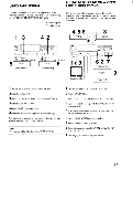
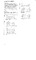
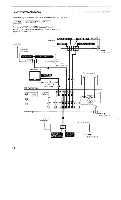
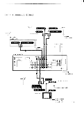
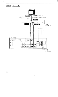
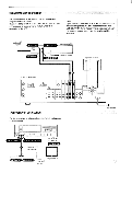
CONNECTION DIAGRAMS Connection notes • The power cord should be connected last of all, first making sure that the MAIN POWER switch is turned off. • When connecting program sources or tape recorders, note that the red jacks of the receiver are for right-channel audio connections, the white jacks for left-channel audio connections and the yellow jacks for video connections. • The cable connectors should be fully inserted into the jacks. A loose connection may cause hum and noise. Before connection, be sure to set the MAIN POWER switch to OFF (n). Connecting cords For connection, use the connecting cords listed below. The numbers in the connection diagrams are keyed to those in the list. White Red (2 phono plugs 2 phono plugs) Supplied with audio equipment or optional Sony RK-74A connecting cord Yellow (phono plug 4-0 phono plug) Optional Sony VMC-1S connecting cord 0 Yellow rcalA White Red Yellow Miniplug (3 phono plugs - phono plug and miniplug) Optional Sony VMC-1MP3 or VMC-2MP3 connecting cord or Yellow cli= White Red Yellow Red (3 phono plugs - 2 phono plugs) Optional Sony VMC-608MS or VMC-609MS connecting cord Red White Yellow (3 phono plugs -- 3 phono plugs) Optional Sony VMC-1P3 or VMC-2P3 connecting cord or White Red (2 phono plugs 2 phono plugs) ,CZkicels ====a3XCE3= Yellow (phono plug - phono plug) Optional Sony RK-74A + VMC-1S connecting cords 18
-
 1
1 -
2
-
3
-
4
-
5
-
6
-
7
-
8
-
9
-
10
-
11
-
12
-
 13
13 -
 14
14 -
 15
15 -
 16
16 -
 17
17 -
 18
18 -
 19
19 -
 20
20 -
 21
21 -
 22
22 -
 23
23 -
24
-
25
-
26
-
27
-
28
-
29
-
30
-
31
-
32
 |
 |
