Sony VGX-XL1A User Guide - Page 31
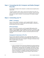
Step 1:, Connecting the DLS Computer and Media Changer/ Recorder, Connecting your TV
 |
View all Sony VGX-XL1A manuals
Add to My Manuals
Save this manual to your list of manuals |
Page 31 highlights
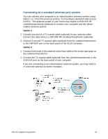
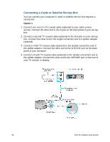
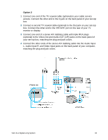
Step 1: Connecting the DLS Computer and Media Changer/ Recorder Connecting the changer to the computer is a simple process requiring only a single cable. Using the supplied i.LINK®1 cable, connect the end without the node to an i.LINK® connector on the back panel of the XL1A computer, and the end with the node to an i.LINK® connector on the back panel of the Media Changer/ Recorder. Step 2: Connecting your TV HDMI™ Connector If your TV has a HDMI™ connector, use the supplied HDMI™ cable and connect one end to your TV and the other end to the HDMI™ connector on the back panel of the DLS computer. DVI-D Connector If your TV has a DVI-D connector, use the supplied HDMI cable and the HDMI™ to DVI-D adapter. Insert the adapter into the DVI-D TV/monitor. Then using the supplied HDMI™ cable, connect one end of the cable to the adapter and the other end to the HDMI™ connector on the back panel of the XL1A computer. Component Connectors (Y, Pb, Pr) If your TV has component connectors, use a component video cable (not supplied) and connect one end to the corresponding video outputs on your TV and on the back panel of the XL1A computer. In this type of connection, there will be separate audio connections. Additional Notes: 1. i.LINK is a trademark of Sony used only to designate that a product contains an IEEE1394 connection. The i.LINK connection may vary depending on the software applications, operating system and compatible i.LINK devices. All products with an i.LINK connection may not communicate with each other. Please refer to the documentation that comes with any device having an i.LINK connection for information on compatibility, operating conditions and proper connection. For information on any Sony device having an i.LINK connection, contact Sony at 1-800-686-7669. 28 VGX-XL1 Digital Living System
-
 1
1 -
2
-
3
-
4
-
5
-
6
-
7
-
8
-
9
-
10
-
11
-
12
-
13
-
14
-
15
-
16
-
17
-
18
-
19
-
20
-
21
-
22
-
23
-
24
-
25
-
 26
26 -
 27
27 -
 28
28 -
 29
29 -
 30
30 -
 31
31 -
 32
32 -
 33
33 -
 34
34 -
 35
35 -
 36
36 -
37
-
38
-
39
-
40
-
41
-
42
-
43
-
44
-
45
-
46
-
47
-
48
-
49
-
50
-
51
-
52
-
53
-
54
-
55
-
56
-
57
-
58
-
59
-
60
-
61
-
62
-
63
-
64
-
65
-
66
-
67
-
68
-
69
-
70
-
71
-
72
-
73
-
74
-
75
-
76
-
77
-
78
-
79
-
80
-
81
-
82
-
83
-
84
-
85
-
86
-
87
-
88
-
89
-
90
-
91
-
92
-
93
-
94
-
95
-
96
-
97
-
98
-
99
-
100
-
101
-
102
-
103
-
104
-
105
-
106
-
107
-
108
-
109
-
110
-
111
-
112
-
113
-
114
-
115
-
116
-
117
-
118
-
119
-
120
-
121
-
122
-
123
-
124
-
125
-
126
-
127
-
128
-
129
-
130
-
131
-
132
-
133
-
134
-
135
-
136
-
137
-
138
-
139
-
140
-
141
-
142
-
143
-
144
-
145
-
146
-
147
-
148
-
149
-
150
-
151
-
152
-
153
-
154
-
155
-
156
-
157
-
158
-
159
-
160
-
161
-
162
-
163
-
164
-
165
-
166
-
167
-
168
-
169
-
170
-
171
-
172
-
173
-
174
-
175
 |
 |