TASCAM DM-24 Installation and Use v 2.0 Manual Addendum - Page 8
Stereo mix output via TDIF, Support of TDIF optional slot card, New input options - daw control
 |
View all TASCAM DM-24 manuals
Add to My Manuals
Save this manual to your list of manuals |
Page 8 highlights
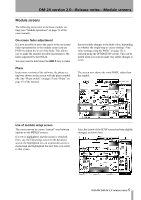
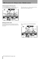
DM-24 version 2.0-Release notes-I/O setup changes In high sampling frequency mode, only aux sends 1 through 4 (AUX1-4) can be selected here. Support of TDIF optional slot card The TDIF optional slot card is now supported for use with the DM-24. However, this does not mean that 32 channels of TDIF digital input are simultaneously available for mixing. Instead, it means that you now have the ability to choose between different sets of TDIF inputs. For example, with a DTRS recorder and an MX-2424 both connected, it is now possible to select either of these as the TDIF input source, using the DM-24 in effect as a digital patch bay. The extra TDIF output channels can also be used if you already have 24 channels of TDIF input that you are mixing in 5.1 format, and you need surround monitoring fed by the extra channels. New input options Previously, channels 25 through 32 were input-only, but from this version, they can be used either as input or as return channels. However, you should note that this does not provide 32-channel digital track mixing (although only 24 returns can be assigned, you can now decide where they go). Stereo mix output via TDIF This allows a TDIF connection (TDIF-3) to output the stereo mix. This can be useful when working with a DAW fitted with a TDIF interface. Additionally, this stereo mix can also be output from the ADAT and SLOT 1 and SLOT 2 outputs. Note however, that in the above example, there is now a "Y"-splitter cable available (CU/PWSPLIT) which can be used to perform a similar function, splitting the TDIF signal into individual INPUT and OUTPUT. In this example, the INPUT comes from the MX-2424 and the OUTPUT is assigned to the DA-78HR. NOTE When a DTRS unit is connected to the DM-24 in this way, it may sometimes happen that the DM-24's display is illuminated, even with the power turned off, because of power being fed through the connection from the DTRS units. If any difficulty is experienced when powering up a system configured in this way, we recommend that the DM-24 is powered up first. Also note that the DTRS remote terminal on the slot card is not operational. Use the DM-24's built-in remote terminal for control of all DTRS units connected to the DM-24. For example, channels 1 through 16 can be used as input channels whose direct outs are used for tracking, and channels 17 through 32 can be used as tape returns. Also note that sources within a block do not necessarily have to be assigned to channels in order (it is possible to "cross over" a pair of input sources, for example). A source may also be assigned to more than one channel. In addition, if a block has been assigned as a return block, sources from this block may also be used within a channel block. For example, if TDIF 1 and TDIF 2 have both been selected as return blocks, channels 1 through 8 may now contain returns from both TDIF 1 and TDIF 2 (previously a group of eight channels could only accept sources from one block at a time). 8 TASCAM DM-24 2.0 release notes
-
 1
1 -
2
-
 3
3 -
 4
4 -
 5
5 -
 6
6 -
 7
7 -
 8
8 -
 9
9 -
 10
10 -
 11
11 -
 12
12 -
 13
13 -
14
-
15
-
16
-
17
-
18
-
19
-
20
-
21
-
22
-
23
-
24
-
25
-
26
-
27
-
28
 |
 |
