TP-Link T1700G-28TQ T1700G-28TQ V1 User Guide - Page 137
Configuration procedure, Application Example for Multicast VLAN
 |
View all TP-Link T1700G-28TQ manuals
Add to My Manuals
Save this manual to your list of manuals |
Page 137 highlights
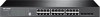
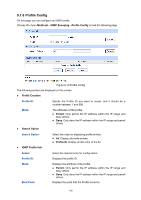
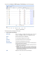
3. Configure the link type of the router port in the multicast VLAN as Tagged otherwise all the member ports in the multicast VLAN cannot receive multicast streams. 4. After a multicast VLAN is created, all the IGMP packets will be processed only within the multicast VLAN. Configuration procedure: Step Operation 1 Enable IGMP snooping function 2 Create a 802.1Q VLAN 3 Configure parameters for multicast VLAN 4 Look over the configuration Description Required. Enable IGMP snooping globally on the switch and for the port on Multicast→IGMP Snooping→Snooping Config and Port Config page. Required. Create a multicast VLAN and add all the member ports and router ports to the VLAN on the VLAN→802.1Q VLAN→VLAN Config page. Configure the link type of the router ports as Tagged. Optional. Enable and configure a multicast VLAN on the Multicast→IGMP Snooping→Multicast VLAN page. It is recommended to keep the default time parameters. If it is successfully configured, the VLAN ID of the multicast VLAN will be displayed in the IGMP Snooping Status table on the Multicast→IGMP Snooping→Snooping Config page. Application Example for Multicast VLAN: Network Requirements Multicast source sends multicast streams via the router, and the streams are transmitted to user A and user B through the switch. Router: Its WAN port is connected to the multicast source; its LAN port is connected to the switch. The multicast packets are transmitted in VLAN3. Switch: Port 3 is connected to the router and the packets are transmitted in VLAN3; port 4 is connected to user A and the packets are transmitted in VLAN4; port 5 is connected to user B and the packets are transmitted in VLAN5. User A: Connected to Port 4 of the switch. User B: Connected to port 5 of the switch. Configure a multicast VLAN, and user A and B receive multicast streams through the multicast VLAN. 127
-
 1
1 -
2
-
3
-
4
-
5
-
6
-
7
-
8
-
9
-
10
-
11
-
12
-
13
-
14
-
15
-
16
-
17
-
18
-
19
-
20
-
21
-
22
-
23
-
24
-
25
-
26
-
27
-
28
-
29
-
30
-
31
-
32
-
33
-
34
-
35
-
36
-
37
-
38
-
39
-
40
-
41
-
42
-
43
-
44
-
45
-
46
-
47
-
48
-
49
-
50
-
51
-
52
-
53
-
54
-
55
-
56
-
57
-
58
-
59
-
60
-
61
-
62
-
63
-
64
-
65
-
66
-
67
-
68
-
69
-
70
-
71
-
72
-
73
-
74
-
75
-
76
-
77
-
78
-
79
-
80
-
81
-
82
-
83
-
84
-
85
-
86
-
87
-
88
-
89
-
90
-
91
-
92
-
93
-
94
-
95
-
96
-
97
-
98
-
99
-
100
-
101
-
102
-
103
-
104
-
105
-
106
-
107
-
108
-
109
-
110
-
111
-
112
-
113
-
114
-
115
-
116
-
117
-
118
-
119
-
120
-
121
-
122
-
123
-
124
-
125
-
126
-
127
-
128
-
129
-
130
-
131
-
 132
132 -
 133
133 -
 134
134 -
 135
135 -
 136
136 -
 137
137 -
 138
138 -
 139
139 -
 140
140 -
 141
141 -
 142
142 -
143
-
144
-
145
-
146
-
147
-
148
-
149
-
150
-
151
-
152
-
153
-
154
-
155
-
156
-
157
-
158
-
159
-
160
-
161
-
162
-
163
-
164
-
165
-
166
-
167
-
168
-
169
-
170
-
171
-
172
-
173
-
174
-
175
-
176
-
177
-
178
-
179
-
180
-
181
-
182
-
183
-
184
-
185
-
186
-
187
-
188
-
189
-
190
-
191
-
192
-
193
-
194
-
195
-
196
-
197
-
198
-
199
-
200
-
201
-
202
-
203
-
204
-
205
-
206
-
207
-
208
-
209
-
210
-
211
-
212
-
213
-
214
-
215
-
216
-
217
-
218
-
219
-
220
-
221
-
222
-
223
-
224
-
225
-
226
-
227
-
228
-
229
-
230
-
231
-
232
-
233
-
234
-
235
-
236
-
237
-
238
-
239
-
240
-
241
-
242
-
243
-
244
-
245
-
246
-
247
-
248
-
249
-
250
-
251
-
252
-
253
-
254
-
255
-
256
-
257
-
258
 |
 |
