TP-Link TL-R460 User Guide - Page 10
Hardware Installation, 2.1 Panel Layout, 2.1.1 The Front Panel - router
 |
UPC - 845973040031
View all TP-Link TL-R460 manuals
Add to My Manuals
Save this manual to your list of manuals |
Page 10 highlights
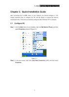
TL-R460 Cable/DSL Router User Guide Chapter 2. Hardware Installation 2.1 Panel Layout 2.1.1 The Front Panel Figure 2-1 The LED indicators displayed on the front panel, the status of these LED indicators represent the device's working circs. For details, please refer to LED Explanation. LED Explanation: Name Status Indication PWR Off No Power On Power on SYS Off The Router has an error On The Router is initializing Flashing The Router is working properly Off There is no device linked to the corresponding port WAN/1-4 (LAN) There are devices linked to the corresponding ports but no On data transmitted or received. Flashing Sending or receiving data over corresponding port 2.1.2 The Rear Panel Figure 2-2 The rear panel contains the following features. ¾ POWER: The Power plug is where you will connect the power adapter. ) Note: 3
-
 1
1 -
2
-
3
-
4
-
 5
5 -
 6
6 -
 7
7 -
 8
8 -
 9
9 -
 10
10 -
 11
11 -
 12
12 -
 13
13 -
 14
14 -
 15
15 -
16
-
17
-
18
-
19
-
20
-
21
-
22
-
23
-
24
-
25
-
26
-
27
-
28
-
29
-
30
-
31
-
32
-
33
-
34
-
35
-
36
-
37
-
38
-
39
-
40
-
41
-
42
-
43
-
44
-
45
-
46
-
47
-
48
-
49
-
50
-
51
-
52
-
53
-
54
-
55
-
56
-
57
-
58
-
59
-
60
-
61
-
62
-
63
-
64
-
65
-
66
-
67
-
68
-
69
-
70
-
71
-
72
-
73
-
74
-
75
-
76
 |
 |
