Weed Eater ONE Owner Manual - Page 21
To Start Engine With A Weak
 |
View all Weed Eater ONE manuals
Add to My Manuals
Save this manual to your list of manuals |
Page 21 highlights
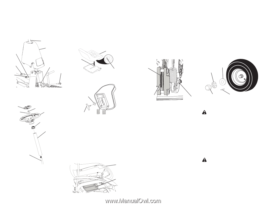
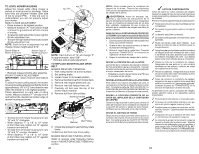
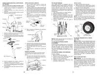
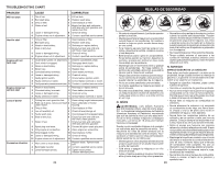
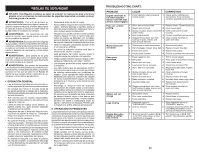
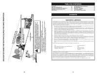
CÓMO CONFIGURAR SU CORTADORA DE CÉSPED INSTALACIÓN DE COLUMNA DE DIRECCIÓN 1. Inserte el eje de dirección en el montaje y apriete bien con el perno, la arandela y la tuerca provistas. 2. Inserte el pasador en el orificio del eje de dirección. 3. Deslice la cubierta de plástico sobre el eje de dirección y en su posición. Eje de dirección Arandela Cubierta de plástico Pasador Tuerca Montaje del eje de dirección Perno INSTALACIÓN DEL ASIENTO 1. Gire el asiento hacia arriba y retírelo del empaque de cartón. Retire el empaque de cartón y deséchelo. 2. Coloque el asiento en la tabla del asiento de manera que el perno de reborde esté colocado sobre el orificio ranurado grande de la tabla. 3. Presione hacia abajo el asiento para colocar el perno de reborde en la ranura y jale el asiento hacia la parte posterior de la cortadora de césped. 4. Gire el asiento y la tabla hacia adelante y ensamble la perilla de ajuste y la arandela plana sin apretar. No apriete. Asiento Tabla de asiento Perno de 02466 reborde 5. Baje el asiento a la posición de operación siéntese sobre él. 4. Deslice la cubierta de espuma de protección del eje de dirección sobre el eje. 5. Coloque las ruedas delanteras de la cortadora de césped de modo que apunten en línea recta hacia adelante. Inserto Tuerca Arandela Volante Adaptador Cubierta de espuma Eje de dirección 6. Retire el adaptador del volante y deslice el adaptador sobre el eje de dirección. 7. Presione el volante en su posición sobre el eje, instale la arandela grande y tuerca; apriete bien la tuerca. 8. Coloque bien el inserto del volante en el centro del volante. Arandela plana 02464 Perilla de ajuste 6. Deslice el asiento hasta que logre una posición cómoda, lo que le permitirá presionar el pedal del embrague/freno hasta el fondo. 7. Retírese del asiento sin mover su posición ajustada. 8. Eleve el asiento y apriete bien la perilla de ajuste. REVISE LA BATERÍA Asegúrese de que la batería esté bien sujetada, y que todos los cables estén bien conectados. • La batería está ubicada debajo del asiento. • La batería se ha cargado por completo en la fábrica antes de su instalación. Asiento Batería 32 TO ADJUST BRAKE Your riding mower is equipped with an adjustable brake system which is mounted on the right side of the transaxle. If riding mower requires more than (4) feet stopping distance in highest gear on a lever dry concrete or paved surface, then brake must be adjusted. 1. Park riding mower on a level surface. 2. Release brake/parking pedal. 3. Measure distance between rotor and brake pad if distance between rotor and brake pad is more than .02" gap brake needs to be adjusted. 4. Tighten caliper nut until .02" gap is reached. REAR WHEEL 1. Block up Rear axle securely. 2. Remove dust cover, retaining ring, wash- er, and square key while pulling tire off. 3. Repair tire and reassemble. 4. Replace square key while putting tire back on, then replace washer and retaining ring securely in axle groove ,when pushing tire back onto shaft reach under and pull chain sprocket toward you to ease tire replacement. NOTE: To seal tire punctures and prevent flat tires due to slow leaks, purchase and use tire sealant. Tire sealant also prevents tire dry rot and corrosion. Rotor Washer Retaining Ring Brake Pad Nut NOTE: Feeler gauge may be necessary to get correct measurement. TO ADJUST STEERING WHEEL ALIGNMENT If steering wheel crossbars are not horizontal (left to right) when wheels are positioned straight forward, move steering wheel and reassemble per instructions in the "INSTALL STEERING COLUMN"section of this manual. TO REMOVE WHEEL FOR REPAIRS FRONT WHEEL 1. Block up front axle securely. 2. Remove dust cover, retaining ring, and washer to allow wheel removal. 3. Repair tire and reassemble. 4. Replace washer and retaining ring securely in axle groove. Dust Cover Square Key (rear wheel only) TO START ENGINE WITH A WEAK BATTERY CAUTION: Lead-acid batteries generate explosive gases. Keep sparks, flame and smokingmaterialsawayfrombatteries. Always wear eye protection when around batteries. If your battery is too weak to start the engine, it should be recharged. (See "BATTERY" in the Maintenance section of this manual). NOTE: This unit is equipped with an engine recoil starting system that can be used if the battery is too weak to start. See "RECOIL STARTING SYSTEM" in operation section of this manual. REPLACING BATTERY WARNING: Do not short battery terminals by allowing a wrench or any other object to contact both terminals at the same time. Before connecting battery, remove metal bracelets, wristwatch bands, rings, etc. Positive terminal must be connected first to prevent sparking from accidental grounding. 21
-
 1
1 -
2
-
3
-
4
-
5
-
6
-
7
-
8
-
9
-
10
-
11
-
12
-
13
-
14
-
15
-
 16
16 -
 17
17 -
 18
18 -
 19
19 -
 20
20 -
 21
21 -
 22
22 -
 23
23 -
 24
24 -
 25
25 -
 26
26
 |
 |