Weider 4990 I Uk Manual - Page 16
Route the Ab Cable 93 through the Upright 5
 |
View all Weider 4990 I manuals
Add to My Manuals
Save this manual to your list of manuals |
Page 16 highlights
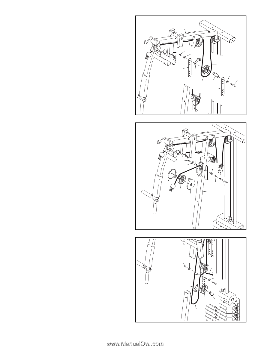
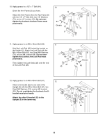
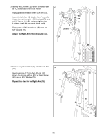
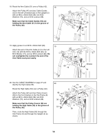
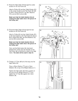
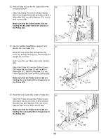
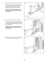
24. Locate the High Cable (53) hanging between the 24 center and rear brackets on the Top Frame (8). Hold a Pulley (42) on the High Cable (53). Attach the Pulley (42) and two Cable Guides (52) between the highest holes in the two Pulley Plates (23) with an M10 x 50mm Bolt (58), two M10 Washers (73), and an M10 Locknut (68). Make sure that the Cable Guides (52) are holding the High Cable (53) in the groove of the Pulley (42). 8 68 73 53 23 52 73 58 42 52 23 25. See the CABLE DIAGRAM on page 27 and identify the Ab Cable (93). 25 Route the Ab Cable (93) through the Upright (5) as shown. Next, route the Ab Cable (93) over a Pulley (42). Attach the Pulley and two Pulley Covers (36) inside the Upright (5) with an M10 x 85mm Bolt (95), two M10 Washers (73), two 22mm Spacers (97), and an M10 Locknut (68). Make sure that the Pulley Covers (36) are holding the Ab Cable (93) in the groove of the Pulley (42). 68 97 73 97 36 42 93 36 73 95 5 26. Route the Ab Cable (93) over a Pulley (42). 26 Attach the Pulley (42) and two Cable Guides (52) to the Offset Double U-bracket (85) with an M10 x 50mm Bolt (58), two M10 Washers (73), and an M10 Locknut (68). Make sure that the Cable Guides (52) are holding the Ab Cable (93) in the groove of the Pulley (42). Then, pull the Ab Cable (93) downward in the indicated location so that there is slack in the Ab Cable. The slack will be used in step 30. 16 68 73 85 52 93 73 58 42 52 Pull
-
 1
1 -
2
-
3
-
4
-
5
-
6
-
7
-
8
-
9
-
10
-
 11
11 -
 12
12 -
 13
13 -
 14
14 -
 15
15 -
 16
16 -
 17
17 -
 18
18 -
 19
19 -
 20
20 -
 21
21 -
22
-
23
-
24
-
25
-
26
-
27
-
28
-
29
-
30
-
31
-
32
 |
 |