Weider 4990 I Uk Manual - Page 18
Route the Low Cable 54 under a Pulley 42.
 |
View all Weider 4990 I manuals
Add to My Manuals
Save this manual to your list of manuals |
Page 18 highlights
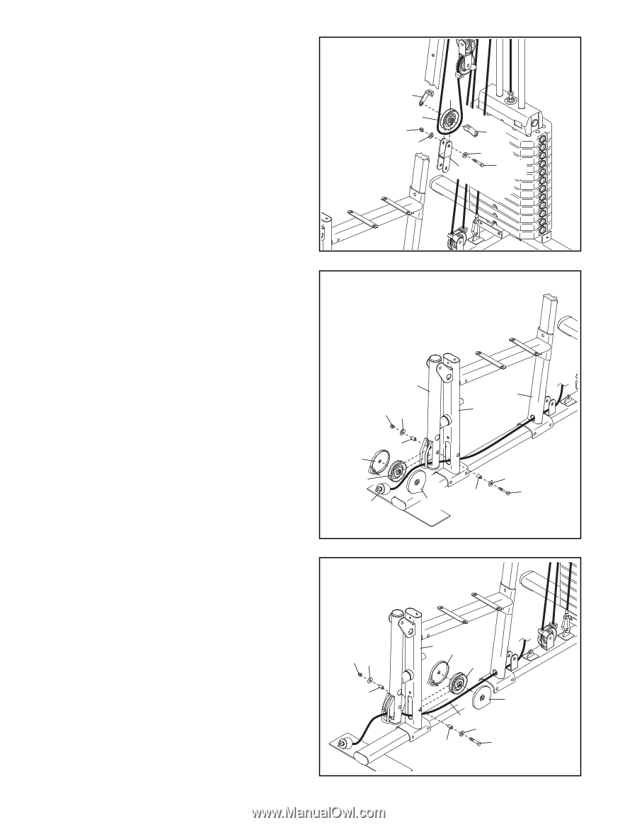
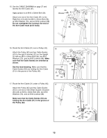
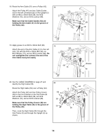
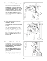
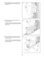
30. Hold a Pulley (42) on the Ab Cable (93) in the 30 indicated location. Attach the Pulley (42) and two Cable Guides (52) to the Double U-bracket (24) with an M10 x 50mm Bolt (58), two M10 Washers (73), and an M10 Locknut (68). Make sure that the Cable Guides (52) are holding the Ab Cable (93) in the groove of the Pulley (42). 52 93 68 73 42 52 73 24 58 31. See the CABLE DIAGRAM on page 27 and identify the Low Cable (54). Route the Low Cable (54) through the Leg Lever (3), through the Leg (21), and through the Upright (5) as shown. Next, route the Low Cable (54) under a Pulley (42). Attach the Pulley (42) and two Pulley Covers (36) inside the Leg Lever (3) with an M10 x 65mm Bolt (37), two M10 Washers (73), two 12mm Spacers (91), and an M10 Locknut (68). Make sure that the Pulley Covers (36) are holding the Low Cable (54) in the groove of the Pulley (42). 31 3 68 73 91 36 42 54 36 5 21 73 91 37 32. Route the Low Cable (54) under a Pulley (42). Attach the Pulley (42) and two Pulley Covers (36) inside the Leg (21) with an M10 x 95mm Bolt (66), two M10 Washers (73), two 27mm Spacers (96), and an M10 Locknut (68). Make sure that the Pulley Covers (36) are holding the Low Cable (54) in the groove of the Pulley (42). 32 68 73 96 18 21 36 42 36 54 73 96 66
-
 1
1 -
2
-
3
-
4
-
5
-
6
-
7
-
8
-
9
-
10
-
11
-
12
-
 13
13 -
 14
14 -
 15
15 -
 16
16 -
 17
17 -
 18
18 -
 19
19 -
 20
20 -
 21
21 -
 22
22 -
 23
23 -
24
-
25
-
26
-
27
-
28
-
29
-
30
-
31
-
32
 |
 |