Weider 7000 Crosstrainer English Manual - Page 20
<75
 |
View all Weider 7000 Crosstrainer manuals
Add to My Manuals
Save this manual to your list of manuals |
Page 20 highlights
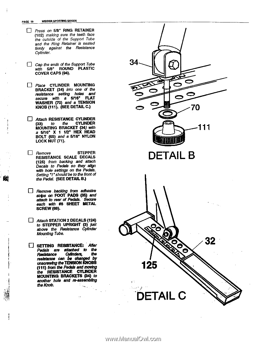
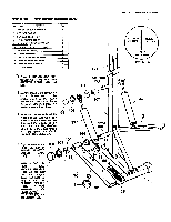
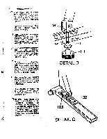
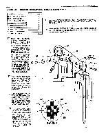
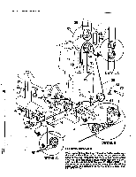
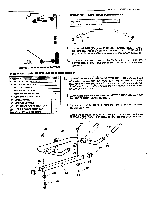
PAGE 19 WSDER SPOR11NG GOODS u Press on 5/8" RING RETAINER (102) making sure the teeth face the outside of the Support Tube and the Ring Retainer is seated firmly against the Resistance Cylinder. u Cap the ends of the Support Tube with 5/8" ROUND PLASTIC COVER CAPS (94). u Place CYLINDER MOUNTING BRACKET (34) Into one of the resistance setting holes and secure with a 5/16" FLAT WASHER (70) and a TENSION KNOB (111). (SEE DETAIL C.) Attach RESISTANCE CYLINDER (33) to the CYLINDER MOUNTING BRACKET (34) with a 5/16* X 1 1/2" HEX HEAD BOLT (65) and a 5/16" NYLON LOCK NUT (71). u Remove STEPPER RESISTANCE SCALE DECALS (125) from backing and attach Decals to Pedals so they align with hole settings on the Pedals. Setting 'I shouldbe to the front of the Pedal. (SEE DETAIL B.) u Remove backing from adhesive strips on FOOT. PADS (35) and attach to rear of Pedals. Secure each with 88 SHEET METAL SCREW (88). u Attach STATION 2 DECALS (124) to STEPPER UPRIGHT (3) just above the Resistance Cylinder Mounting Tube. SETTING RESISTANCE: After Pedals are attached to the Resistance Cylinders, the resistance can be changed by unscrewing the TENSION KNOBS. (111) from the Pedals andmoving the RESISTANCE CYUNDER MOUNTING BRACKETS (34) to another hole and re-assembling the Knob. 34 T 70
-
 1
1 -
2
-
3
-
4
-
5
-
6
-
7
-
8
-
9
-
10
-
11
-
12
-
13
-
14
-
 15
15 -
 16
16 -
 17
17 -
 18
18 -
 19
19 -
 20
20 -
 21
21 -
 22
22 -
 23
23 -
 24
24 -
 25
25 -
26
-
27
-
28
 |
 |