Weider 7000 Crosstrainer English Manual - Page 23
Flat,washer
 |
View all Weider 7000 Crosstrainer manuals
Add to My Manuals
Save this manual to your list of manuals |
Page 23 highlights
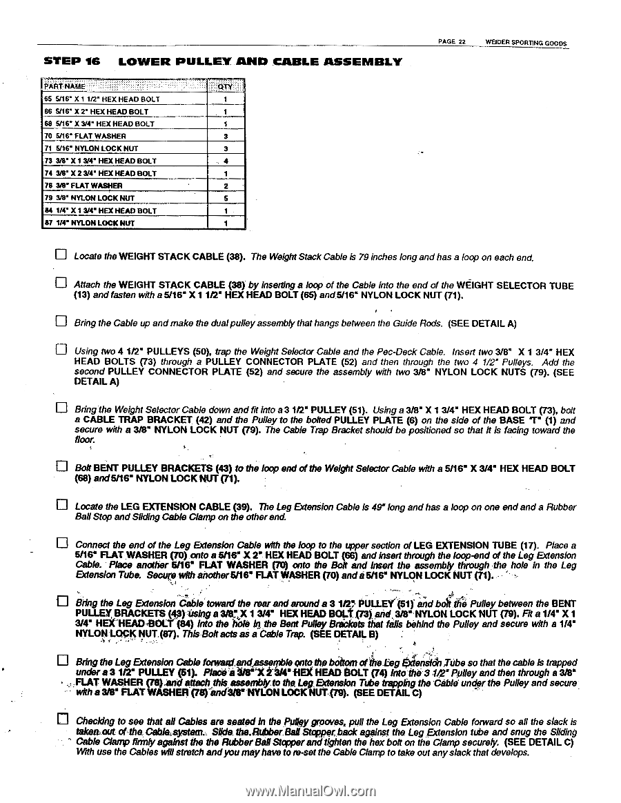
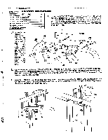
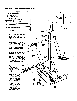
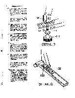
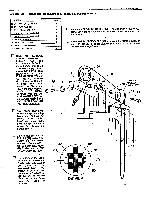
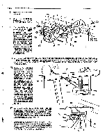
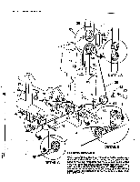
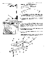
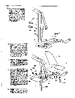
STEP 16 LOWER PULLEY.AND CABLE ASSEMBLY PART NAME ' '' .: :''' 65 5/16" X 1 1/2" HEX HEAD BOLT 66 5/16" X 2' HEX HEAD BOLT 68 5/16" X 3/4" HEX HEAD BOLT 70 5/16" FLAT WASHER 71 5/16' NYLON LOCK NUT 73 3/8" X 13/4" HEX HEAD BOLT 74 3/8" X 2 3/4' HEX HEAD BOLT 78 3/8" FLAT WASHER 79 3/8" NYLON LOCK NUT 84 1/4" X 1 3/4' HEX HEAD BOLT 87 1/4" NYLON LOCK NUT , . ::.QTY 1 1 1 3 3 4 1 2 5 1 1 PAGE 22 WEIDER SPORTING GOODS D Locate the WEIGHT STACK CABLE (38). The Weight Stack Cable Is 79 inches longandhas a loop on each end. u Attach the WEIGHT STACK CABLE (38) by inserting a loop of the Cable into the end of the WEIGHT SELECTOR TUBE (13) and fasten with a 5/16" X11/2" HEX HEAD BOLT (65) and5/16" NYLON LOCK NUT (71). u Bring the Cable up andmake the dualpulleyassembly that hangs between the Guide Rods. (SEE DETAIL A) El Using two 4 1/2" PULLEYS (50), trap the Weight Selector Cable and the Pec-Deck Cable. Insert two 3/8" X 1 3/4" HEX HEAD BOLTS (73) through a PULLEY CONNECTOR PLATE (52) and then through the two 4 1/2' Pulleys. Add the second PULLEY CONNECTOR PLATE (52) and secure the assembly with two 3/8" NYLON LOCK NUTS (79). (SEE DETAIL A) Bring the Weight Selector Cable down and fit into a 3 1/2" PULLEY (51). Using a 3/8" X 13/4" HEX HEAD BOLT (73), bolt a CABLE TRAP BRACKET (42) and the Pulley to the bolted PULLEY PLATE (6) on the side of the BASE 7" (1) and secure with a 3/8" NYLON LOCK NUT (79). The Cable Trap Bracket should be positioned so that it is facing toward the floor. Bolt BENT PULLEY BRACKETS (43) to the loop end of the Weight Selector Cable with a 5/16" X 3/4" HEX HEAD BOLT (68) and5/16" NYLON LOCK NUT (71). Locate the LEG EXTENSION CABLE (39). The Leg Extension Cable is 491long andhas a loop on one endand a Rubber Ball Stop and Sliding Cable Clamp on the other end. Connect the end of the Leg Extension Cable with the loop to the upper section of LEG EXTENSION TUBE (17). Place a 5/16" FLAT WASHER (70) onto a 5/16" .X 2, HEX HEAD BOLT (66) and insert through the loop-end of the Leg Extension Cable. Place another 5/16' FLAT WASHER (70) onto the Bolt and insert the assembly through: the hole in the Leg Extension Tube. Secure with another5/16' FLAT,WASHER (70) ands5/16" NYLON LOCK NUT (71). u Bring the Leg Extension Cable towardthe rear andaround a 312' PULLEY.(51) annboithe Pulley between the BENT PULLEY BRACKETS (43)1ising a 3its,x 13/4" HEX HEAD BOLT(73).and.3/8•.NYLON LOCK NUT (79). Fit a 1/46 X 1 3/4" HEX"HEAD,BOLY (84) into the hole !tithe Bent Pulley Brackets that fells behind the Pulley and secure with a 1/4' NYLON LOCK NUT:(87). This Bolt acts as a Cable Trap. (SEE DETAIL B) : • A O Bring the LegExtension Cable fonvatztand,asserpble onto the bOttom of'ihe.liegEiterialal,TUbe so that the cable is trapped under a 312" PULLEY (51). Pladen 9/8"'"X t3/4" HEX HEAD BOLT (74) intnilla .4,2° Pulley and then through a 3/8" „„FLATWASHER (79).80 attach,this assembly.to the Leg.Extension Tube trapping the *Cable under the Pulley andsecure with a 3/8" FLAT WASHER (79)-ind3firNYLONLOCK NUT.(79). (SEE DETAIL C) O Checking to see that all Cables are seated h? the Pulley grooves, pull the Leg Extension Cable forward so all the slack is taken.out of the. Cable system. Slide the.Rubber Ball Stopper back against the LegExtension tube and snug the Sliding Cable Clamp firmly against the the Rubber Ball Stopper and tighten the hex bolt on the Clamp securely (SEE DETAIL C) With use the Cables willstretch andyoumayhave to re-set the Cable Clamp to take out anyslack that develops.
-
 1
1 -
2
-
3
-
4
-
5
-
6
-
7
-
8
-
9
-
10
-
11
-
12
-
13
-
14
-
15
-
16
-
17
-
 18
18 -
 19
19 -
 20
20 -
 21
21 -
 22
22 -
 23
23 -
 24
24 -
 25
25 -
 26
26 -
 27
27 -
 28
28
 |
 |