Weider X5 Power Guide English Manual - Page 10
Important
 |
View all Weider X5 Power Guide manuals
Add to My Manuals
Save this manual to your list of manuals |
Page 10 highlights
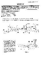
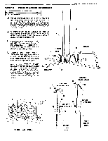
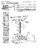
PAGE 8 WEIDER SPORTING GOODS IMPORTANT SOME OF THE ASSEMBLIES HAVE BEEN DONE AT THE FACTORY FOR YOUR CONVENIENCE. THESE PRE-ASSEMBLED PARTS HAVE ONLY BEEN FASTENED FINGER TIGHT. YOU WILL INSTRUCTED TO TIGHTEN EACH OF THESE ASSEMBLIES DURING THE STEP INSTRUCTIONS. DOUBLE CHECK THESE ASSEMBLIES AND TIGHTEN THEM AS INSTRUCTED. STEP II BASE FRAME ASSEMBLY PART NAME 51 5116" NYLON LOCK NUT 52 5116" X 21/2" HEX HEAD BOLT 56 5/16" X 21/2" CARRIAGE BOLT 80 2" SQUARE PLASTIC INSERT CAP QTY 2 2 2 4 D Begin by capping the ends of the CENTER BASE (1) with 2" SQUARE PLASTIC INSERT CAPS (80). u Cap the one end of both the FRONT BASE (2) and the REAR BASE (3) with 2" SQUARE PLASTIC INSERT CAPS (80). 80 1\.-3 FRONT 80 00 2 52 0 REAR 51 11:1 \3 80 80 52 56 56 Assemble the FRONT BASE (2) and the REAR BASE (3) to the middle of the CENTER BASE (1) using 5/16" X 2 1/2" HEX HEAD BOLTS (52) to bolt through the brackets of the Front Base, through the Center Base, and then through the brackets of the Rear Base. Secure with 5/16" NYLON LOCK NUTS (51). (SEE DETAIL A) Insert two 5/16" X 2 1/2" CARRIAGE BOLTS (56) up through the bottom of the REAR BASE (3) in the hole locations near the CENTER BASE (1). This assembly will be completed in a later step. 51 56 52 DETAIL A
-
 1
1 -
2
-
3
-
4
-
 5
5 -
 6
6 -
 7
7 -
 8
8 -
 9
9 -
 10
10 -
 11
11 -
 12
12 -
 13
13 -
 14
14 -
 15
15 -
16
-
17
-
18
-
19
-
20
-
21
-
22
-
23
-
24
-
25
-
26
-
27
-
28
-
29
-
30
-
31
-
32
-
33
-
34
-
35
-
36
 |
 |
