Weider X5 Power Guide English Manual - Page 20
Stepper, Assembly, Holes, Should, Inside
 |
View all Weider X5 Power Guide manuals
Add to My Manuals
Save this manual to your list of manuals |
Page 20 highlights
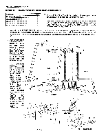
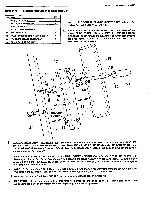
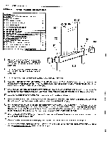
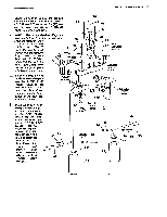
PAGE 18 WEIDER SPORTING GOODS STEP 10 STEPPER ASSEMBLY PART NAME QTY 51 5/16" NYLON LOCK NUT 2 58 5/16" x 11/2" HEX HEAD BOLT 2 60 3/8" FLAT WASHER 2 75 1/2" LONG SELF TAPPING PHILLIPS HEAD SCREWS 2 85 1" ROUND PLASTIC COVER CAP 2 92 5/8" I.D. X 11/4" FLAIR END PLASTIC BUSHING 2 95 1" SPRING RETAINER RING 2 13 111 5/8" SPRING RETAINER RING 2 112 5/8" ROUND PLASTIC COVER CAP 2 113 3/8" THREAD KNOB 2 103 Slide the STEPPER PEDALS (44) onto the 1" Stepper Pivot Tube at the base of the STEPPER UPRIGHT (13). Note that the Pedal should be assembled with the series of holes to the inside. Using a 1" ROUND PLASTIC COVER CAP (85) as an aid, drive a 1" SPRING RETAINER RING (95) onto the Pivot Tube to secure the PEDALS (44) in place. Note that the teeth in the Spring Retainers are tilted slightly to one side. The teeth should be away from the Pivot Tube as it is drive on. Tap in place with a hammer. Attach the molded PLASTIC PEDAL THREADS (45) to the top of .the STEPPER PEDALS (44) with 1/2" LONG SELF TAPPING PHILLIPS HEAD SCREWS (75). Fit a 5/8" I.D. X 1 1/4" FLAIR END PLASTIC BUSHING (92) onto the Cylinder Pivot Tube on the STEPPER UPRIGHT (13). STEPPER PIVOT TUBE 95 85 85 95 44 HOLES SHOULD BE ON THE INSIDE 75 44 45 OLES SHOULD BE ON THE INSIDE 75 45 CYLINDER PIVOT TUBE 13 92 111 112 46 46 0 0 \
-
 1
1 -
2
-
3
-
4
-
5
-
6
-
7
-
8
-
9
-
10
-
11
-
12
-
13
-
14
-
 15
15 -
 16
16 -
 17
17 -
 18
18 -
 19
19 -
 20
20 -
 21
21 -
 22
22 -
 23
23 -
 24
24 -
 25
25 -
26
-
27
-
28
-
29
-
30
-
31
-
32
-
33
-
34
-
35
-
36
 |
 |
