Yamaha AW4416 Owner's Manual - Page 83
D.ST IN, WCLK IN, Using the AW4416 as the word clock master, word clock master
 |
View all Yamaha AW4416 manuals
Add to My Manuals
Save this manual to your list of manuals |
Page 83 highlights
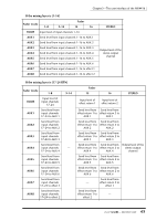
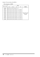
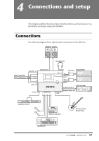
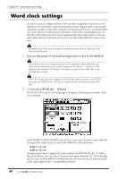
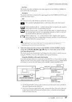
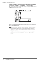
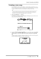
Chapter4-Connections and setup ❍ D.ST IN The word clock data included in the input signal from the DIGITAL STEREO IN jack will be the clock source. ❍ WCLK IN The word clock data included in the input signal from the WORD CLOCK IN jack will be the clock source. ❍ INT The internal clock of the AW4416 will be the clock source. The currently highlighted button is selected as the word clock source. Buttons marked with an × symbol indicate that no digital audio signal is being input from the corresponding slot/jack. Buttons marked with a / symbol indicate that either no digital audio signal is being input from the corresponding slot/jack, or that it is not synchronized with the AW4416's internal clock. Buttons without an × or / symbol indicate that a digital audio signal is being input from the corresponding slot/jack, and that it is synchronized with the AW4416's internal clock. If the AW4416 is set to be an MTC slave, it is not possible for the AW4416 to simultaneously be set as the word clock slave. 3. Select the desired clock source in the WORD CLOCK SOURCE area by using the CURSOR keys to move the cursor to the corresponding button. The clock source you should select will depend on the system in which you are using the AW4416. Here we will explain some typical situations. ❍ Using the AW4416 as the word clock master If no external digital device is connected to the AW4416, or if you wish to use the AW4416 as the word clock master so that external devices such as a digital MTR will follow it, turn on the INT button of the WORD CLOCK SOURCE area. PROFESSIONAL AUDIO WORKSTATION OPTION SLOT 1 Word clock Sync Out Digital MTR (word clock slave) Word clock AW4416 (word clock master) WORD CLOCK SOURCE= INT OPTION SLOT 2 Sync In Digital MTR (word clock slave) • Set the digital MTR so that it will synchronize to the word clock included in the input signal from the AW4416. • If you are using two digital MTR units, connect the Sync Out jack of the first to the Sync In jack of the second as shown here, so that the second digital MTR will follow the first. 69 - Operation Guide
-
 1
1 -
2
-
3
-
4
-
5
-
6
-
7
-
8
-
9
-
10
-
11
-
12
-
13
-
14
-
15
-
16
-
17
-
18
-
19
-
20
-
21
-
22
-
23
-
24
-
25
-
26
-
27
-
28
-
29
-
30
-
31
-
32
-
33
-
34
-
35
-
36
-
37
-
38
-
39
-
40
-
41
-
42
-
43
-
44
-
45
-
46
-
47
-
48
-
49
-
50
-
51
-
52
-
53
-
54
-
55
-
56
-
57
-
58
-
59
-
60
-
61
-
62
-
63
-
64
-
65
-
66
-
67
-
68
-
69
-
70
-
71
-
72
-
73
-
74
-
75
-
76
-
77
-
 78
78 -
 79
79 -
 80
80 -
 81
81 -
 82
82 -
 83
83 -
 84
84 -
 85
85 -
 86
86 -
 87
87 -
 88
88 -
89
-
90
-
91
-
92
-
93
-
94
-
95
-
96
-
97
-
98
-
99
-
100
-
101
-
102
-
103
-
104
-
105
-
106
-
107
-
108
-
109
-
110
-
111
-
112
-
113
-
114
-
115
-
116
-
117
-
118
-
119
-
120
-
121
-
122
-
123
-
124
-
125
-
126
-
127
-
128
-
129
-
130
-
131
-
132
-
133
-
134
-
135
-
136
-
137
-
138
-
139
-
140
-
141
-
142
-
143
-
144
-
145
-
146
-
147
-
148
-
149
-
150
-
151
-
152
-
153
-
154
-
155
-
156
-
157
-
158
-
159
-
160
-
161
-
162
-
163
-
164
-
165
-
166
-
167
-
168
-
169
-
170
-
171
-
172
-
173
-
174
-
175
-
176
-
177
-
178
-
179
-
180
-
181
-
182
-
183
-
184
-
185
-
186
-
187
-
188
-
189
-
190
-
191
-
192
-
193
-
194
-
195
-
196
-
197
-
198
-
199
-
200
-
201
-
202
-
203
-
204
-
205
-
206
-
207
-
208
-
209
-
210
-
211
-
212
-
213
-
214
-
215
-
216
-
217
-
218
-
219
-
220
-
221
-
222
-
223
-
224
-
225
-
226
-
227
-
228
-
229
-
230
-
231
-
232
-
233
-
234
-
235
-
236
-
237
-
238
-
239
-
240
-
241
-
242
-
243
-
244
-
245
-
246
-
247
-
248
-
249
-
250
-
251
-
252
-
253
-
254
-
255
-
256
-
257
-
258
-
259
-
260
-
261
-
262
-
263
-
264
-
265
-
266
-
267
-
268
-
269
-
270
-
271
-
272
-
273
-
274
-
275
-
276
-
277
-
278
-
279
 |
 |
