Yamaha CLP-150 Owner's Manual - Page 112
CLP-150: Keyboard Stand, Assembly
 |
View all Yamaha CLP-150 manuals
Add to My Manuals
Save this manual to your list of manuals |
Page 112 highlights
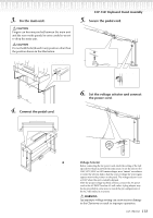
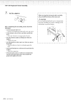
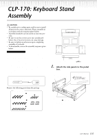
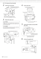
CLP-150: Keyboard Stand Assembly CAUTION • Be careful not to confuse parts, and be sure to install all parts in the correct direction. Please assemble in accordance with the sequence given below. • Assembly should be carried out by at least two persons. • Be sure to use the correct screw size, as indicated below. Use of incorrect screws can cause damage. • Be sure to tighten up all screws upon completing assembly of each unit. • To disassemble, reverse the assembly sequence given below. Have a Phillips-head (+) screwdriver ready. Remove the following parts from the package. Assembly Parts 6 × 25 mm long screws ×4 1 4 × 20 mm tapping screws ×4 4 6 × 16 mm short screws ×6 2 Cord holders ×2 4 × 12 mm thin screws ×2 3 Main unit 1. Attach the side panels to the pedal box. side panel (left) (1) Untie and straighten out the bundled cord attached to the bottom of the pedal box. side panel (right) (2) Use the four 6×25 mm long screws 1to attach the pedal box. First attach one side panel, then attach the other side panel. 2. Attach the rear panel. (2) Secure the top of the rear panel to the side panel brackets using two 4×12 mm 3 thin screws. L R (1) Place the bottom edge of the rear panel in the grooves of the legs, and then fasten the upper edge. (3) Secure the bottom of the rear panel to the pedal box using four 4×20 mm 4 tapping screws. Side panel (left) Rear panel Side panel (right) Pedal box Bundled pedal cord inside AC power cord 112 CLP-170/150
-
 1
1 -
2
-
3
-
4
-
5
-
6
-
7
-
8
-
9
-
10
-
11
-
12
-
13
-
14
-
15
-
16
-
17
-
18
-
19
-
20
-
21
-
22
-
23
-
24
-
25
-
26
-
27
-
28
-
29
-
30
-
31
-
32
-
33
-
34
-
35
-
36
-
37
-
38
-
39
-
40
-
41
-
42
-
43
-
44
-
45
-
46
-
47
-
48
-
49
-
50
-
51
-
52
-
53
-
54
-
55
-
56
-
57
-
58
-
59
-
60
-
61
-
62
-
63
-
64
-
65
-
66
-
67
-
68
-
69
-
70
-
71
-
72
-
73
-
74
-
75
-
76
-
77
-
78
-
79
-
80
-
81
-
82
-
83
-
84
-
85
-
86
-
87
-
88
-
89
-
90
-
91
-
92
-
93
-
94
-
95
-
96
-
97
-
98
-
99
-
100
-
101
-
102
-
103
-
104
-
105
-
106
-
 107
107 -
 108
108 -
 109
109 -
 110
110 -
 111
111 -
 112
112 -
 113
113 -
 114
114 -
 115
115 -
 116
116 -
 117
117 -
118
-
119
-
120
-
121
-
122
-
123
-
124
 |
 |
