Yamaha CLP-150 Owner's Manual - Page 113
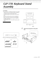
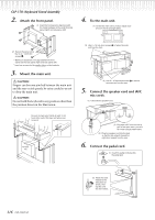
CLP-150: Keyboard Stand Assembly
 |
View all Yamaha CLP-150 manuals
Add to My Manuals
Save this manual to your list of manuals |
Page 113 highlights
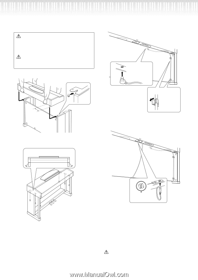
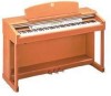
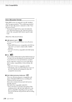
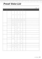
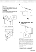
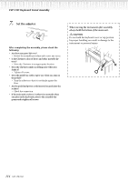
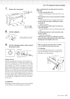
127 R PEDAL 3. Fix the main unit. CAUTION Fingers can become pinched between the main unit and the rear or side panels, be extra careful so as not to drop the main unit. CAUTION Do not hold the keyboard in any position other than the position shown in the illustration. Be sure to place your hands at least 10 cm from either end of the main unit when positioning it. At least 10cm 4. Connect the pedal cord. (1) Center the main unit to produce equal clearance on the left and right sides. CLP-150: Keyboard Stand Assembly 5. Secure the pedal cord. (1) Insert the pedal cord plug to the pedal connector from the front. (2) Attach the cord holders to the rear panel as shown, then clip the cord into the holders. 6. Set the voltage selector and connect the power cord. AC INLET 110 220 (2) Use 6×16 mm short screws 2 to secure the main unit from the front. 240 Voltage Selector Before connecting the AC power cord, check the setting of the voltage selector which is provided in some areas. To set the selector for 110V, 127V, 220V or 240V main voltages, use a "minus" screwdriver to rotate the selector dial so that the correct voltage for your region appears next to the pointer on the panel. The voltage selector is set at 240V when the unit is initially shipped. After the proper voltage has been selected, connect the AC power cord to the AC INLET and an AC wall outlet. A plug adaptor may be also provided in some areas to match the pin configuration of the AC wall outlets in your area. WARNING An improper voltage setting can cause serious damage to the Clavinova or result in improper operation. CLP-170/150 113
-
 1
1 -
2
-
3
-
4
-
5
-
6
-
7
-
8
-
9
-
10
-
11
-
12
-
13
-
14
-
15
-
16
-
17
-
18
-
19
-
20
-
21
-
22
-
23
-
24
-
25
-
26
-
27
-
28
-
29
-
30
-
31
-
32
-
33
-
34
-
35
-
36
-
37
-
38
-
39
-
40
-
41
-
42
-
43
-
44
-
45
-
46
-
47
-
48
-
49
-
50
-
51
-
52
-
53
-
54
-
55
-
56
-
57
-
58
-
59
-
60
-
61
-
62
-
63
-
64
-
65
-
66
-
67
-
68
-
69
-
70
-
71
-
72
-
73
-
74
-
75
-
76
-
77
-
78
-
79
-
80
-
81
-
82
-
83
-
84
-
85
-
86
-
87
-
88
-
89
-
90
-
91
-
92
-
93
-
94
-
95
-
96
-
97
-
98
-
99
-
100
-
101
-
102
-
103
-
104
-
105
-
106
-
107
-
 108
108 -
 109
109 -
 110
110 -
 111
111 -
 112
112 -
 113
113 -
 114
114 -
 115
115 -
 116
116 -
 117
117 -
 118
118 -
119
-
120
-
121
-
122
-
123
-
124
 |
 |