Yamaha CVP-69 Owner's Manual - Page 147
Den Pedalkasten E am Lautsprecherkasten
 |
View all Yamaha CVP-69 manuals
Add to My Manuals
Save this manual to your list of manuals |
Page 147 highlights
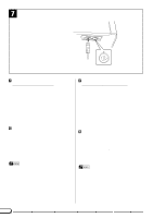
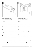
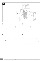
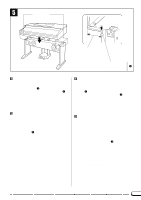
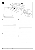
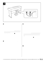
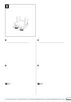
4 4 x 20 mm (small round-head) screws Rundkopfschrauben (4 x 20 mm) Petites vis de 4 x 20 mm (à tête ronde) 3 Tornillos de 4 x 20 mm (pequeños de cabeza redonda) 6 x 20 mm (large flat-head) screw Senkschraube (6 x 20 mm) Grosses vis de 6 x 20 mm (à tête plate) 2 Tornillo de 6 x 20 mm (grande de cabeza plana) B C VAttach the pedal box (E) to the speaker box (B). Secure the pedal box (E) to the speaker box (B) using one 6 x 20 mm (large flat-head) screw 2 for each bottom bracket and two 4 x 20 mm (small round-head) screws 3 for each rear bracket. Make sure that the pedal cord passes through the recess in the top of the pedal assembly and the speaker cord is extending out to the rear from the top of the speaker box (see illustration). BAttach the main keyboard unit (A). (Part 1) Gently lower the main keyboard unit (A) onto the speaker box (B) and stand assembly so that the rear of the main unit is positioned about 10cm behind the back of the side panel. WATCH YOUR FINGERS WHEN DOING THIS!! Insert one 6 x 20 mm (large flat-head) screw 2 into the innermost hole leaving about 1cm of the screw protruding on each side of the main unit's bottom panel. These screws will slide into the rear side-panel brackets in step 6. * Keep your fingers away from the area marked "Danger Zone" in the illustrations when lowering the main keyboard unit onto the stand assembly. VDen Pedalkasten (E) am Lautsprecherkasten (B) festschrauben. Schrauben Sie den Pedalkasten mit jeweils einer Senkschraube (6 x 20 mm) 2 für die beiden unteren Halterungen und zwei Rundkopfschrauben (4 x 20 mm) 3 für die beiden hinteren Halterungen an den Lautsprecherkasten (B). Achten Sie dabei darauf, daß das Pedalkabel oben aus dem einen Bein des Pedalkastens ragt und das Lautsprecherkabel nach hinten gelegt ist, wie in der Abbildung gezeigt. BDie Haupteinheit (A) montieren. (Teil 1) Setzen Sie die Haupteinheit (A) vorsichtig so auf den Lautsprecherkasten und die Seitenwände, daß ihre Hinterseite etwa 10 cm über den Hinterkanten der Seitenwände übersteht. VORSICHT! KLEMMEN SIE SICH DABEI NICHT DIE FINGER EIN! Drehen Sie hinten an der Unterseite der Haupteinheit links und rechts jeweils eine Senkschraube (6 x 20 mm) 2 in die innere Bohrung, so daß noch etwa 1 cm Gewinde hervorsteht. Diese Schrauben greifen in Schritt 6 in die hinteren Halterungen der Seitenwände. * Halten Sie beim Aufsetzen der Haupteinheit auf die Ständerbaugruppe von dem in der Abbildung mit "Gefahrenzone" gekennzeichneten Bereich fern. 144
-
 1
1 -
2
-
3
-
4
-
5
-
6
-
7
-
8
-
9
-
10
-
11
-
12
-
13
-
14
-
15
-
16
-
17
-
18
-
19
-
20
-
21
-
22
-
23
-
24
-
25
-
26
-
27
-
28
-
29
-
30
-
31
-
32
-
33
-
34
-
35
-
36
-
37
-
38
-
39
-
40
-
41
-
42
-
43
-
44
-
45
-
46
-
47
-
48
-
49
-
50
-
51
-
52
-
53
-
54
-
55
-
56
-
57
-
58
-
59
-
60
-
61
-
62
-
63
-
64
-
65
-
66
-
67
-
68
-
69
-
70
-
71
-
72
-
73
-
74
-
75
-
76
-
77
-
78
-
79
-
80
-
81
-
82
-
83
-
84
-
85
-
86
-
87
-
88
-
89
-
90
-
91
-
92
-
93
-
94
-
95
-
96
-
97
-
98
-
99
-
100
-
101
-
102
-
103
-
104
-
105
-
106
-
107
-
108
-
109
-
110
-
111
-
112
-
113
-
114
-
115
-
116
-
117
-
118
-
119
-
120
-
121
-
122
-
123
-
124
-
125
-
126
-
127
-
128
-
129
-
130
-
131
-
132
-
133
-
134
-
135
-
136
-
137
-
138
-
139
-
140
-
141
-
 142
142 -
 143
143 -
 144
144 -
 145
145 -
 146
146 -
 147
147 -
 148
148 -
 149
149 -
 150
150 -
 151
151 -
 152
152 -
153
-
154
-
155
-
156
-
157
-
158
-
159
-
160
-
161
-
162
-
163
 |
 |
