Yamaha CVP-69 Owner's Manual - Page 149
Das Lautsprecherkabel und das Pedalkabel
 |
View all Yamaha CVP-69 manuals
Add to My Manuals
Save this manual to your list of manuals |
Page 149 highlights
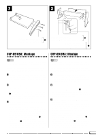
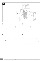
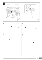
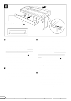
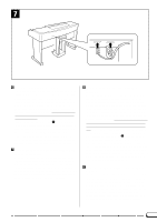
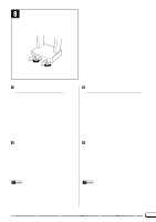
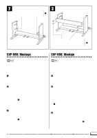
6 A 6 x 20 mm (large flat-head) screw Senkschraube (6 x 20 mm) Grosses vis de 6 x 20 mm (à tête plate) 2 A Tornillo de 6 x 20 mm (grande de cabeza plana) A C NAttach the main keyboard unit. (Part 2) With the protruding screw heads on the bottom panel of the main unit positioned behind the side-panel rear brackets, slide the main keyboard unit forward until the screw heads stop against the end of the slot in the rear brackets. Align the holes in the bottom of the main unit with those in the front side-panel brackets (also center the main unit to produce an equal clearance on the left and right sides, as shown in the illustrations), then secure the main keyboard unit to the stand assembly using two 6 x 20 mm (large flat-head) screws 2 screwed through the front bracket and then firmly tightening the two protruding screws that slid into the rear brackets. Put the speaker box cover back in place with the "Velcro" on the cover and speaker box. (Make sure that the upper edge of the cover fits snugly against the under side of the main unit.) MConnect the speaker cord and pedal cord. Insert the speaker cord connector into the corresponding socket on the right (closest to the pedal box) of the keyboard unit. Plug the pedal cord connector into the socket on the left (farthest from the pedal box) of the keyboard unit. Note that both connectors must be inserted with the protruding clip facing the rear of the main unit. NDie Haupteinheit montieren. (Teil 2) Positionieren Sie die Haupteinheit so auf der Ständerbaugruppe, daß die beiden eingedrehten Schrauben hinter den hinteren Halterungen an den Seitenwänden zu liegen kommen, und schieben Sie dann nach vorn, bis die Schrauben bis zum Anschlag in den Halterungsschlitzen sitzen. Bringen Sie die Bohrungen der vorderen Halterungen mit denen an der Unterseite der Haupteinheit zur Deckung (achten Sie auch darauf, daß die Haupteinheit mittig positioniert ist, d.h. links und rechts gleichviel übersteht, wie in der Abbildung gezeigt), und schrauben Sie die Haupteinheit dann mit zwei weiteren Senkschrauben (6 x 20 mm) 2 an den vorderen Halterungen fest, um danach die beiden bereits eingedrehten Schrauben fest anzuziehen. Bringen Sie nun die Bespannung wieder an, indem Sie die Klettband-Gegenstücke an Bespannungsrahmen und Lautsprecherkasten aufeinander ausrichten. (Die Oberkante des Bespannungsrahmens muß bündig an der Unterseite der Haupteinheit anliegen.) MDas Lautsprecherkabel und das Pedalkabel anschließen. Schließen Sie das Lautsprecherkabel an die rechte (dem Pedalkasten am nächsten gelegene) Buchse an an der Unterseite der Haupteinheit an. Das Pedalkabel schließen Sie an die linke (am weitesten vom Pedalkasten entfernte) Buchse an. Die beiden Stecker müssen mit der Führungsnase in Richtung Rückseite (der Haupteinheit) in die jeweilige Buchse gesteckt werden. 146
-
 1
1 -
2
-
3
-
4
-
5
-
6
-
7
-
8
-
9
-
10
-
11
-
12
-
13
-
14
-
15
-
16
-
17
-
18
-
19
-
20
-
21
-
22
-
23
-
24
-
25
-
26
-
27
-
28
-
29
-
30
-
31
-
32
-
33
-
34
-
35
-
36
-
37
-
38
-
39
-
40
-
41
-
42
-
43
-
44
-
45
-
46
-
47
-
48
-
49
-
50
-
51
-
52
-
53
-
54
-
55
-
56
-
57
-
58
-
59
-
60
-
61
-
62
-
63
-
64
-
65
-
66
-
67
-
68
-
69
-
70
-
71
-
72
-
73
-
74
-
75
-
76
-
77
-
78
-
79
-
80
-
81
-
82
-
83
-
84
-
85
-
86
-
87
-
88
-
89
-
90
-
91
-
92
-
93
-
94
-
95
-
96
-
97
-
98
-
99
-
100
-
101
-
102
-
103
-
104
-
105
-
106
-
107
-
108
-
109
-
110
-
111
-
112
-
113
-
114
-
115
-
116
-
117
-
118
-
119
-
120
-
121
-
122
-
123
-
124
-
125
-
126
-
127
-
128
-
129
-
130
-
131
-
132
-
133
-
134
-
135
-
136
-
137
-
138
-
139
-
140
-
141
-
142
-
143
-
 144
144 -
 145
145 -
 146
146 -
 147
147 -
 148
148 -
 149
149 -
 150
150 -
 151
151 -
 152
152 -
 153
153 -
 154
154 -
155
-
156
-
157
-
158
-
159
-
160
-
161
-
162
-
163
 |
 |
