Yamaha HTR 5860 MCXSP10 Manual - Page 74
Option Menu, Option, Adisplay, Bmemory, Guard
 |
UPC - 027108922096
View all Yamaha HTR 5860 manuals
Add to My Manuals
Save this manual to your list of manuals |
Page 74 highlights
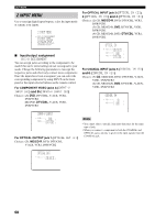
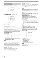
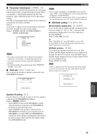
p p p p SET MENU 3 OPTION MENU Use to adjust the optional system parameters. 3 OPTION MENU . A)DISPLAY SET B)MEMORY GUARD C)PARAM. INI D)MULTI ZONE SET [ ]/[ ]:Up/Down [ENTER]:Enter ■ Display settings A)DISPLAY SET A)DISPLAY SET . DIMMER;;;;;;;;;0 VIDEO CONV.;;;ON OSD SHIFT;;;;;;0 GRAY BACK;;;AUTO CMPNT OSD;;;;;ONXM INFO [ ]/[ ]:Up/Down []:sELECT Dimmer DIMMER Use to adjust the brightness of the front panel display. Choices: -4 to 0 Video conversion VIDEO CONV. Use this feature to turn on/off conversion of composite (VIDEO) signals to both S-video and component signals. This allows you to output converted video signals from the S VIDEO or COMPONENT VIDEO jacks when no S-video or component signals are input. This feature also converts S-Video signals to component signals when no component signals are input. Choices: ON, OFF • Select OFF not to convert any signals (except S-video signals to composite signals). • Select ON to convert composite signals to S-video and component signals, and to convert S-video signals to component signals. • Regardless of the setting, S-video signals are always converted to composite signals. Notes • Converted video signals are only output to the MONITOR OUT jacks. When recording you must make the same type of video connections (i.e., S-video) between each component. • When converting composite video or S-Video signals from a VCR to component video signals, the picture quality may suffer depending on your VCR. OSD shift OSD SHIFT Use to adjust the vertical position of the OSD. Choices: +5 (downward) to -5 (upward) • Press + to lower the position of the OSD. • Press - to raise the position of the OSD. Gray back GRAY BACK Selecting AUTO for the on-screen display setting displays a gray background when there's no video signal input. Nothing is displayed if OFF is selected. Choices: AUTO, OFF Notes • When only the component video signals are input, the OSD is not displayed if GRAY BACK is set to OFF. To display the OSD with component video signal input, set GRAY BACK to AUTO while the OSD mode (see page 58) is set to "Full display". • When video signals are not being input, set GRAY BACK to AUTO to display the OSD. Component OSD CMPNT OSD Use this feature to turn on/off OSD output to the COMPONENT VIDEO MONITOR OUT jacks when using the SET MENU. Choices: ON, OFF • Select ON to output the OSD signals from COMPONENT VIDEO MONITOR OUT jacks. • Select OFF if you do not want to output the OSD signals from COMPONENT VIDEO MONITOR OUT jacks. Note SET MENU functions even when OFF is selected. ■ Memory guard B)MEMORY GUARD Use this feature to prevent accidental changes to DSP program parameter values and other system settings. Choices: ON, OFF B)MEMORY GUARD )OFF ON []:Select [ENTER]:Return Select ON to protect: • DSP program parameters • All SET MENU items • All speaker levels • The on-screen display (OSD) mode Note When MEMORY GUARD is set to ON, you cannot select any other SET MENU items. 70
-
 1
1 -
2
-
3
-
4
-
5
-
6
-
7
-
8
-
9
-
10
-
11
-
12
-
13
-
14
-
15
-
16
-
17
-
18
-
19
-
20
-
21
-
22
-
23
-
24
-
25
-
26
-
27
-
28
-
29
-
30
-
31
-
32
-
33
-
34
-
35
-
36
-
37
-
38
-
39
-
40
-
41
-
42
-
43
-
44
-
45
-
46
-
47
-
48
-
49
-
50
-
51
-
52
-
53
-
54
-
55
-
56
-
57
-
58
-
59
-
60
-
61
-
62
-
63
-
64
-
65
-
66
-
67
-
68
-
 69
69 -
 70
70 -
 71
71 -
 72
72 -
 73
73 -
 74
74 -
 75
75 -
 76
76 -
 77
77 -
 78
78 -
 79
79 -
80
-
81
-
82
-
83
-
84
-
85
-
86
-
87
-
88
-
89
-
90
-
91
-
92
-
93
-
94
-
95
-
96
-
97
-
98
-
99
-
100
-
101
-
102
-
103
 |
 |