Yamaha HTR-6180BL Owner's Manual - Page 35
Using the remote control
 |
UPC - 027108930107
View all Yamaha HTR-6180BL manuals
Add to My Manuals
Save this manual to your list of manuals |
Page 35 highlights
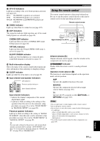
PREPARATION D SP A B indicators Light up according to the set of front speakers activated (see page 43). SP A: The FRONT A speakers are activated. SP B: The FRONT B speakers are activated. SP A B: The FRONT A and FRONT B speakers are activated. E ZONE2 indicator Lights up when Zone 2 is turned on (see page 107). F DSP indicators The respective indicator lights up when any of the sound field programs are selected (see page 48). CINEMA DSP indicator Lights up when you select a CINEMA DSP sound field program (see page 48). VIRTUAL indicator Lights up when the Virtual CINEMA DSP mode is active (see page 51). SILENT CINEMA indicator Lights up when headphones are connected and a sound field program is selected (see page 51). G Multi-information display Shows the name of the current sound field program and other information when adjusting or changing settings. H SLEEP indicator Lights up while the sleep timer is on (see page 47). I Input channel and speaker indicators LFE L CR SL SB SR SBL SBR LFE indicator Presence speaker indicators Input channel indicators Input channel indicators • Indicate the channel components of the current digital input signal. • Light up or flash according to the settings of the speakers when this unit is in the automatic setup procedure (see page 32) or in the "BASIC MENU" in "MANUAL SETUP" (see page 89). Presence speaker indicators Light up or flash according to the setting of "EXTRA SP ASSIGN" when this unit is in the automatic setup procedure (see page 32) or in the "BASIC MENU" in "MANUAL SETUP" (see page 87). y You can make settings for the presence and surround back speakers automatically by running "AUTO SETUP" (see page 32) or manually by adjusting settings for "SUR.B L/R SP" (see page 88) in "SPEAKER SET". Connections Using the remote control The remote control transmits a directional infrared ray. Be sure to aim the remote control directly at the remote control sensor on this unit during operation. Remote control sensor Approximately 6 m (20 ft) 30 30 Infrared window (1) Outputs infrared control signals. Aim this window at the component you want to operate. BTRANSMIT indicator Flashes while the remote control is sending infrared signals. Operation mode selector (F) The function of some buttons depends on the operation mode selector position. AMP Operates the amplifier function of this unit. SOURCE Operates the component selected with an input selector button (see page 103). TV Operates the TV assigned to either 4DTV/CBL or 4PHONO (see page 102). Notes • Do not spill water or other liquids on the remote control. • Do not drop the remote control. • Do not leave or store the remote control in the following types of conditions: - places of high humidity, such as near a bath - places of high temperatures, such as near a heater or stove - places of extremely low temperatures - dusty places • To set the remote control codes for other components, see page 104. English 31 En
-
 1
1 -
2
-
3
-
4
-
5
-
6
-
7
-
8
-
9
-
10
-
11
-
12
-
13
-
14
-
15
-
16
-
17
-
18
-
19
-
20
-
21
-
22
-
23
-
24
-
25
-
26
-
27
-
28
-
29
-
 30
30 -
 31
31 -
 32
32 -
 33
33 -
 34
34 -
 35
35 -
 36
36 -
 37
37 -
 38
38 -
 39
39 -
 40
40 -
41
-
42
-
43
-
44
-
45
-
46
-
47
-
48
-
49
-
50
-
51
-
52
-
53
-
54
-
55
-
56
-
57
-
58
-
59
-
60
-
61
-
62
-
63
-
64
-
65
-
66
-
67
-
68
-
69
-
70
-
71
-
72
-
73
-
74
-
75
-
76
-
77
-
78
-
79
-
80
-
81
-
82
-
83
-
84
-
85
-
86
-
87
-
88
-
89
-
90
-
91
-
92
-
93
-
94
-
95
-
96
-
97
-
98
-
99
-
100
-
101
-
102
-
103
-
104
-
105
-
106
-
107
-
108
-
109
-
110
-
111
-
112
-
113
-
114
-
115
-
116
-
117
-
118
-
119
-
120
-
121
-
122
-
123
-
124
-
125
-
126
-
127
-
128
-
129
-
130
-
131
-
132
-
133
-
134
-
135
-
136
-
137
-
138
-
139
-
140
-
141
-
142
-
143
-
144
-
145
-
146
-
147
-
148
-
149
-
150
-
151
-
152
 |
 |
