ZyXEL GS1920 Series User Guide - Page 72
Interface Setup
 |
View all ZyXEL GS1920 Series manuals
Add to My Manuals
Save this manual to your list of manuals |
Page 72 highlights
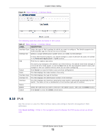
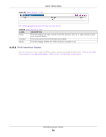
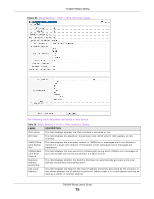
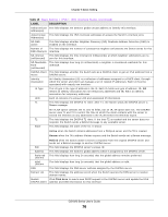
Chapter 8 Basic Setting The following table describes the labels in this screen. Table 16 Basic Setting > PoE Setup LABEL PoE Mode DESCRIPTION Select the power management mode you want the Switch to use. Port PD • Classification - Select this if you want the Switch to reserve the Max Power (mW) to each PD according to the priority level. If the total power supply runs out, PDs with lower priority do not get power to function. • Consumption - Select this if you want the Switch to manage the total power supply so that each connected PD gets a resource. However, the power allocated by the Switch may be less than the Max Power (mW) of the PD. PDs with higher priority also get more power than those with lower priority levels. This is the port index number. Select this to provide power to a PD connected to the port. PD Priority If left unchecked, the PD connected to the port cannot receive power from the Switch. When the total power requested by the PDs exceeds the total PoE power budget on the Switch, you can set the PD priority to allow the Switch to provide power to ports with higher priority. Select Critical to give the highest PD priority on the port. Select High to set the Switch to assign the remaining power to the port after all critical priority ports are served. Max Power (mW) Apply Cancel Select Low to set the Switch to assign the remaining power to the port after all critical and high priority ports are served. This field displays the maximum amount of power the PD could use from the Switch on this port. Click Apply to save your changes to the Switch's run-time memory. The Switch loses these changes if it is turned off or loses power, so use the Save link on the top navigation panel to save your changes to the non-volatile memory when you are done configuring. Click Cancel to begin configuring this screen afresh. 8.9 Interface Setup An IPv6 address is configured on a per-interface basis. The interface can support virtual interface (for example, a VLAN). The Switch supports the VLAN interface type for IPv6 at the time of writing. Use this screen to set IPv6 interfaces on which you can configure an IPv6 address to access and manage the Switch. Click Basic Setting > Interface Setup in the navigation panel to display the configuration screen. GS1920 Series User's Guide 72
-
 1
1 -
2
-
3
-
4
-
5
-
6
-
7
-
8
-
9
-
10
-
11
-
12
-
13
-
14
-
15
-
16
-
17
-
18
-
19
-
20
-
21
-
22
-
23
-
24
-
25
-
26
-
27
-
28
-
29
-
30
-
31
-
32
-
33
-
34
-
35
-
36
-
37
-
38
-
39
-
40
-
41
-
42
-
43
-
44
-
45
-
46
-
47
-
48
-
49
-
50
-
51
-
52
-
53
-
54
-
55
-
56
-
57
-
58
-
59
-
60
-
61
-
62
-
63
-
64
-
65
-
66
-
 67
67 -
 68
68 -
 69
69 -
 70
70 -
 71
71 -
 72
72 -
 73
73 -
 74
74 -
 75
75 -
 76
76 -
 77
77 -
78
-
79
-
80
-
81
-
82
-
83
-
84
-
85
-
86
-
87
-
88
-
89
-
90
-
91
-
92
-
93
-
94
-
95
-
96
-
97
-
98
-
99
-
100
-
101
-
102
-
103
-
104
-
105
-
106
-
107
-
108
-
109
-
110
-
111
-
112
-
113
-
114
-
115
-
116
-
117
-
118
-
119
-
120
-
121
-
122
-
123
-
124
-
125
-
126
-
127
-
128
-
129
-
130
-
131
-
132
-
133
-
134
-
135
-
136
-
137
-
138
-
139
-
140
-
141
-
142
-
143
-
144
-
145
-
146
-
147
-
148
-
149
-
150
-
151
-
152
-
153
-
154
-
155
-
156
-
157
-
158
-
159
-
160
-
161
-
162
-
163
-
164
-
165
-
166
-
167
-
168
-
169
-
170
-
171
-
172
-
173
-
174
-
175
-
176
-
177
-
178
-
179
-
180
-
181
-
182
-
183
-
184
-
185
-
186
-
187
-
188
-
189
-
190
-
191
-
192
-
193
-
194
-
195
-
196
-
197
-
198
-
199
-
200
-
201
-
202
-
203
-
204
-
205
-
206
-
207
-
208
-
209
-
210
-
211
-
212
-
213
-
214
-
215
-
216
-
217
-
218
-
219
-
220
-
221
-
222
-
223
-
224
-
225
-
226
-
227
-
228
-
229
-
230
-
231
-
232
-
233
-
234
-
235
-
236
-
237
-
238
-
239
-
240
-
241
-
242
-
243
-
244
-
245
-
246
-
247
-
248
-
249
-
250
-
251
-
252
-
253
-
254
-
255
-
256
-
257
-
258
-
259
-
260
-
261
-
262
-
263
-
264
-
265
-
266
-
267
-
268
-
269
-
270
-
271
-
272
-
273
-
274
-
275
-
276
-
277
-
278
-
279
-
280
-
281
-
282
-
283
-
284
-
285
-
286
-
287
-
288
-
289
-
290
-
291
-
292
-
293
-
294
-
295
-
296
-
297
-
298
-
299
-
300
-
301
-
302
-
303
-
304
-
305
-
306
-
307
-
308
-
309
-
310
-
311
-
312
-
313
-
314
-
315
-
316
-
317
-
318
-
319
-
320
-
321
-
322
-
323
-
324
-
325
-
326
-
327
-
328
-
329
-
330
-
331
-
332
-
333
-
334
-
335
-
336
-
337
-
338
-
339
-
340
-
341
-
342
-
343
-
344
-
345
-
346
-
347
-
348
-
349
-
350
-
351
-
352
-
353
-
354
-
355
-
356
-
357
-
358
-
359
-
360
-
361
-
362
-
363
-
364
-
365
-
366
-
367
-
368
-
369
-
370
-
371
-
372
-
373
-
374
-
375
-
376
-
377
-
378
-
379
-
380
-
381
 |
 |
