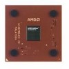
AMD AX2000DMT3C User Guide
AMD AX2000DMT3C - Athlon XP 1.67 GHz Processor Manual
 |
View all AMD AX2000DMT3C manuals
Add to My Manuals
Save this manual to your list of manuals |
AMD AX2000DMT3C manual content summary:
- AMD AX2000DMT3C | User Guide - Page 1
Preliminary Information AMD AthlonTM XP Processor Model 6 Data Sheet Publication # 24309 Rev: E Issue Date: March 2002 - AMD AX2000DMT3C | User Guide - Page 2
AMD") products. AMD makes no representations or warranties with respect to the accuracy or completeness of the contents of this publication and reserves the right to make changes to specifications time without notice. Trademarks AMD, the AMD Arrow logo, AMD Athlon, AMD Duron, and combinations thereof - AMD AX2000DMT3C | User Guide - Page 3
-March 2002 Preliminary Information AMD Athlon™ XP Processor Model 6 Data Sheet Contents Revision History xi 1 Overview 1 1.1 QuantiSpeed™ Architecture Summary 2 2 Interface Signals 5 2.1 Overview 5 2.2 Signaling Technology 5 2.3 Push-Pull (PP) Drivers 6 2.4 AMD Athlon™ System Bus Signals - AMD AX2000DMT3C | User Guide - Page 4
Preliminary Information AMD Athlon™ XP Processor Model 6 Data Sheet 24309E-March 2002 8 Signal and Power-Up Requirements 43 8.1 Power-Up Requirements 43 Signal Sequence and Timing Description 43 Clock Multiplier Selection (FID[3:0 46 8.2 Processor Warm Reset Requirements 46 Northbridge Reset - AMD AX2000DMT3C | User Guide - Page 5
24309E-March 2002 Preliminary Information AMD Athlon™ XP Processor Model 6 Data Sheet VCCA Pin 73 VID[4:0] Pins 73 VREFSYS Pin 74 ZN and ZP Pins 74 11 Ordering Information 75 Standard AMD Athlon XP Processor Model 6 Products 75 Appendix A Conventions and Abbreviations 77 Signals and Bits - AMD AX2000DMT3C | User Guide - Page 6
Preliminary Information AMD Athlon™ XP Processor Model 6 Data Sheet 24309E-March 2002 vi Table of Contents - AMD AX2000DMT3C | User Guide - Page 7
2002 Preliminary Information AMD Athlon™ XP Processor Model 6 Data Sheet List of Figures Figure 1. Typical AMD Athlon™ XP Processor Model 6 System Block Diagram 3 Figure 2. Logic Symbol Diagram 7 Figure 3. AMD Athlon XP Processor Model 6 Power Management States 9 Figure 4. AMD Athlon System Bus - AMD AX2000DMT3C | User Guide - Page 8
Preliminary Information AMD Athlon™ XP Processor Model 6 Data Sheet 24309E-March 2002 viii List of Figures - AMD AX2000DMT3C | User Guide - Page 9
24309E-March 2002 Preliminary Information AMD Athlon™ XP Processor Model 6 Data Sheet List of Tables Table 1. Table 2. Table 3. Table 4. Table 5. the AMD Athlon XP Processor Model 6 OPGA Package 48 Pin Name Abbreviations 54 Cross-Reference by Pin Location 60 FID[3:0] Clock Multiplier Encodings - AMD AX2000DMT3C | User Guide - Page 10
Preliminary Information AMD Athlon™ XP Processor Model 6 Data Sheet 24309E-March 2002 x List of Tables - AMD AX2000DMT3C | User Guide - Page 11
Voltage and Current," on page 31 ■ In Chapter 11, revised Figure 16, "OPN Example for the AMD Athlon™ XP Processor Model 6' on page 75 Revisions to the AMD Athlon™ XP Processor Model 6 Data Sheet since October 2001 include the following: ■ In Chapter 6, revised Table 1, "Thermal Design Power," on - AMD AX2000DMT3C | User Guide - Page 12
Preliminary Information AMD Athlon™ XP Processor Model 6 Data Sheet 24309E-March 2002 xii Revision History - AMD AX2000DMT3C | User Guide - Page 13
an integrated, exclusive L2 cache, which supports the growing processor and system bandwidth requirements of emerging software, graphics, I/O, and memory technologies. The high-speed execution core of the AMD Athlon XP processor model 6 includes multiple x86 instruction decoders, a dual-ported 128 - AMD AX2000DMT3C | User Guide - Page 14
loaded. The AMD Athlon XP processor model 6 delivers excellent system performance in a cost-effective, industry-standard form factor. The AMD Athlon processor model 6 is compatible with motherboards based on Socket A. Figure 1 on page 3 shows a typical AMD Athlon processor system block diagram - AMD AX2000DMT3C | User Guide - Page 15
24309E-March 2002 Preliminary Information AMD Athlon™ XP Processor Model 6 Data Sheet Thermal Monitor AMD Athlon™ XP Processor Model 6 AMD Athlon System Bus AGP Bus System Controller (Northbridge) Memory Bus PCI Bus AGP SDRAM or DDR Peripheral Bus Controller (Southbridge) LAN SCSI - AMD AX2000DMT3C | User Guide - Page 16
Preliminary Information AMD Athlon™ XP Processor Model 6 Data Sheet 24309E-March 2002 4 Overview Chapter 1 - AMD AX2000DMT3C | User Guide - Page 17
24309E-March 2002 Preliminary Information AMD Athlon™ XP Processor Model 6 Data Sheet 2 Interface Signals 2.1 Overview The AMD Athlon™ system bus architecture is designed to deliver excellent data movement bandwidth for nextgeneration x86 platforms as well as the high-performance required by - AMD AX2000DMT3C | User Guide - Page 18
-Pull (PP) Drivers The AMD Athlon XP processor model 6 supports Push-Pull (PP) drivers. The system logic configures the processor with the configuration parameter called SysPushPull (1=PP). The impedance of the PP drivers is set to match the impedance of the motherboard by two external resistors - AMD AX2000DMT3C | User Guide - Page 19
[14:2]# SADDOUTCLK# AMD Athlon™ XP Processor Model 6 PROCRDY CLKFWDRST CONNECT STPCLK# RESET# VID[4:0] COREFB COREFB# PWROK FID[3:0] FERR IGNNE# INIT# INTR NMI A20M# SMI# FLUSH# THERMDA THERMDC PICCLK PICD[1:0] Figure 2. Logic Symbol Diagram Voltage Control Frequency Control Legacy Thermal - AMD AX2000DMT3C | User Guide - Page 20
Preliminary Information AMD Athlon™ XP Processor Model 6 Data Sheet 24309E-March 2002 8 Logic Symbol Diagram Chapter 3 - AMD AX2000DMT3C | User Guide - Page 21
the power management control system of the AMD Athlon™ XP processor model 6. The power management features of the processor are compliant with the ACPI 1.0b and ACPI 2.0 specifications. 4.1 Power Management States The AMD Athlon XP processor model 6 supports low-power Halt and Stop Grant states - AMD AX2000DMT3C | User Guide - Page 22
Preliminary Information AMD Athlon™ XP Processor Model 6 Data Sheet 24309E-March 2002 Working State Halt State Stop Grant States 10 The following sections provide an overview of the power management states. For more details, refer to the AMD Athlon™ and AMD Duron™ System Bus Specification, order# - AMD AX2000DMT3C | User Guide - Page 23
STPCLK# is deasserted, the processor initiates a connect of the AMD Athlon system bus if it is disconnected. After the processor enters the Working state, any pending interrupts are recognized and serviced and the processor resumes execution at the instruction boundary where STPCLK# was initially - AMD AX2000DMT3C | User Guide - Page 24
Information AMD Athlon™ XP Processor Model 6 Data Sheet serviced, the processor returns to the same state as when it entered the Probe state (Halt or Stop Grant state). When probe activity is completed the processor only returns to a low-power state after the Northbridge disconnects the AMD Athlon - AMD AX2000DMT3C | User Guide - Page 25
24309E-March 2002 Preliminary Information AMD Athlon™ XP Processor Model 6 Data Sheet 4.2 Connect and Disconnect Protocol Significant power savings of the processor only occur if the processor is disconnected from the system bus by the Northbridge while in the Halt or Stop Grant state. The - AMD AX2000DMT3C | User Guide - Page 26
AMD Athlon™ XP Processor Model 6 Data Sheet 24309E-March 2002 Note: In response to Halt special cycles, the Northbridge passes the Halt special cycle to the PCI bus or Southbridge immediately. The processor information, see the AMD Athlon™ and AMD Duron™ System Bus Specification, order# 21902 for - AMD AX2000DMT3C | User Guide - Page 27
24309E-March 2002 Preliminary Information AMD Athlon™ XP Processor Model 6 Data Sheet Figure 4 shows STPCLK# assertion resulting in the processor in the Stop Grant state and the AMD Athlon system bus disconnected. STPCLK# AMD Athlon™ System Bus Stop Grant CONNECT PROCRDY CLKFWDRST PCI Bus - AMD AX2000DMT3C | User Guide - Page 28
Preliminary Information AMD Athlon™ XP Processor Model 6 Data Sheet 24309E-March 2002 Figure 5 shows the signal sequence of events that takes the processor out of the Stop Grant state, connects the processor to the AMD Athlon system bus, and puts the processor into the Working state. ST PCLK # - AMD AX2000DMT3C | User Guide - Page 29
AMD Athlon™ XP Processor Model 6 Data Sheet Connect State Diagram Figure 6 below and Figure 7 on page 18 show the Northbridge and processor 3 A Connect special cycle from the processor. 4 No probes are pending. 5 PROCRDY is deasserted. 6 A probe needs service. 7 PROCRDY is asserted. Three SYSCLK - AMD AX2000DMT3C | User Guide - Page 30
Information AMD Athlon™ XP Processor Model 6 Data Sheet 24309E-March 2002 1 Disconnect Pending 3/A Connect 2/B Disconnect 6/B Connect Pending 2 5 Connect Pending 1 4/C Condition 1 CONNECT is deasserted by the Northbridge (for a previously sent Halt or Stop Grant special cycle). 2 Processor - AMD AX2000DMT3C | User Guide - Page 31
Information AMD Athlon™ XP Processor Model 6 Data Sheet 4.3 Clock Control The processor implements a Clock Control (CLK_Ctl) MSR (address C001_001Bh) that determines the internal clock divisor when the AMD Athlon system bus is disconnected. Refer to the AMD Athlon™ and AMD Duron™ Processors BIOS - AMD AX2000DMT3C | User Guide - Page 32
Preliminary Information AMD Athlon™ XP Processor Model 6 Data Sheet 24309E-March 2002 20 Power Management Chapter 4 - AMD AX2000DMT3C | User Guide - Page 33
March 2002 Preliminary Information AMD Athlon™ XP Processor Model 6 Data Sheet 5 CPUID Support AMD Athlon™ XP processor model 6 version and feature set recognition can be performed through the use of the CPUID instruction, that provides complete information about the processor-vendor, type, name - AMD AX2000DMT3C | User Guide - Page 34
Preliminary Information AMD Athlon™ XP Processor Model 6 Data Sheet 24309E-March 2002 22 CPUID Support Chapter 5 - AMD AX2000DMT3C | User Guide - Page 35
see the AMD Athlon™ Processor Thermal, Mechanical, and Chassis Cooling Design Guide, order# 23794, and the cooling guidelines on http://www.amd.com. Table 1 shows the thermal design power specifications for the AMD Athlon XP processor model 6. Table 1. Thermal Design Power Model Number Frequency - AMD AX2000DMT3C | User Guide - Page 36
Preliminary Information AMD Athlon™ XP Processor Model 6 Data Sheet 24309E-March 2002 24 Thermal Design Chapter 6 - AMD AX2000DMT3C | User Guide - Page 37
AMD Athlon™ XP Processor Model 6 Data Sheet 7 Electrical Data 7.1 Conventions The conventions used in this chapter are as follows: ■ Current specified as being sourced by the processor is negative. ■ Current specified as being sunk by the processor Frequency FID[3:0] See "Frequency - AMD AX2000DMT3C | User Guide - Page 38
Preliminary Information AMD Athlon™ XP Processor Model 6 Data Sheet 24309E-March 2002 Table 2. Interface Signal Groupings (continued) Signal Group Signals Southbridge RESET#, INTR, NMI, SMI#, INIT#, A20M#, FERR, IGNNE#, STPCLK#, FLUSH# JTAG TMS, TCK, TRST#, TDI, TDO Test PLLBYPASS#, - AMD AX2000DMT3C | User Guide - Page 39
. 2. Measured at 2.5 V. 7.6 Decoupling See the AMD Athlon™ Processor-Based Motherboard Design Guide, order# 24363, or contact your local AMD office for information about the decoupling required on the motherboard for use with the AMD Athlon™ XP processor model 6. Chapter 7 Electrical Data 27 - AMD AX2000DMT3C | User Guide - Page 40
Preliminary Information AMD Athlon™ XP Processor Model 6 Data Sheet 24309E-March 2002 7.7 VCC_CORE Characteristics Table 6 shows the AC and DC characteristics for VCC_CORE. measurements are taken differentially at the COREFB/COREFB# pins. Units mV mV mV mV µs µs 28 Electrical Data Chapter 7 - AMD AX2000DMT3C | User Guide - Page 41
24309E-March 2002 Preliminary Information AMD Athlon™ XP Processor Model 6 Data Sheet VCC_CORE_MAX_AC Figure 8 shows the processor core voltage (VCC_CORE) waveform response to perturbation. The tMIN_AC (negative AC transient excursion time) and tMAX_AC (positive AC transient excursion time) - AMD AX2000DMT3C | User Guide - Page 42
TSTORAGE Description AMD Athlon™ XP processor model 6 core supply AMD Athlon XP processor model 6 PLL supply Voltage on any signal pin Storage temperature of processor Min -0.5 V -0.5 V -0.5 V -40ºC Max VCC_CORE Max + 0.5 V VCCA Max + 0.5 V VCC_CORE Max + 0.5 V 100ºC 30 Electrical Data Chapter - AMD AX2000DMT3C | User Guide - Page 43
Preliminary Information AMD Athlon™ XP Processor Model 6 Data Sheet 7.9 VCC_CORE Voltage and Current Table 8 shows the voltage and current for the AMD Athlon XP processor model 6 during normal and reduced power states. Table 8. VCC_CORE Voltage and Current Model Number Frequency (MHz) Nominal - AMD AX2000DMT3C | User Guide - Page 44
Preliminary Information AMD Athlon™ XP Processor Model 6 Data Sheet 24309E-March 2002 7.10 SYSCLK and SYSCLK# AC VCC_CORE/2 ±100 mV CPIN Capacitance * 4 12 pF Note: * The following processor inputs have twice the listed capacitance because they connect to two input pads-SYSCLK and - AMD AX2000DMT3C | User Guide - Page 45
Information AMD Athlon™ XP Processor Model 6 Data Sheet Table 10 shows the SYSCLK/SYSCLK# differential clock AC characteristics of the AMD Athlon XP processor model 6. Table 10. SYSCLK and SYSCLK# AC Characteristics Symbol Parameter Description Minimum Maximum Units Notes Clock Frequency - AMD AX2000DMT3C | User Guide - Page 46
AMD Athlon™ XP Processor Model 6 Data Sheet 24309E-March 2002 7.11 AMD Athlon™ System Bus AC and DC Characteristics Table 11 shows the DC characteristics of the AMD Athlon system bus used by the AMD Athlon XP processor model 6. Table 11. AMD Athlon are specific to motherboard design - AMD AX2000DMT3C | User Guide - Page 47
-March 2002 Preliminary Information AMD Athlon™ XP Processor Model 6 Data Sheet The AC characteristics of the AMD Athlon system bus are shown in Table 12. The parameters are grouped based on the source or destination of the signals involved. Table 12. AMD Athlon™ System Bus AC Characteristics - AMD AX2000DMT3C | User Guide - Page 48
AMD Athlon™ XP Processor Model 6 Data Sheet 24309E-March 2002 7.12 General AC and DC Characteristics Table 13 shows the AMD Athlon XP processor operation. 10. This value is dependent on RSTCLK frequency, divisors, Low Power mode, and core frequency. 11. Reassertions of the signal within this time - AMD AX2000DMT3C | User Guide - Page 49
24309E-March 2002 Preliminary Information AMD Athlon™ XP Processor Model 6 Data Sheet Table 13. General AC and in normal mode operation. 10. This value is dependent on RSTCLK frequency, divisors, Low Power mode, and core frequency. 11. Reassertions of the signal within this time are not guaranteed - AMD AX2000DMT3C | User Guide - Page 50
Preliminary Information AMD Athlon™ XP Processor Model 6 Data Sheet 24309E-March 2002 7.13 Open Drain Test Circuit Figure 11 is a test circuit that may be used on for VID and FID pins IOL = -12 mA for APIC pins Figure 11. General ATE Open Drain Test Circuit 38 Electrical Data Chapter 7 - AMD AX2000DMT3C | User Guide - Page 51
24309E-March 2002 Preliminary Information AMD Athlon™ XP Processor Model 6 Data Sheet 7.14 Thermal Diode Characteristics Thermal Diode Electrical Characteristics. Table 14 shows the AMD Athlon XP processor model 6 electrical characteristics of the on-die thermal diode. Table 14. Thermal Diode - AMD AX2000DMT3C | User Guide - Page 52
■ AMD Thermal, Mechanical, and Chassis Cooling Design Guide, order# 23794 ■ http://www1.amd.com/products/athlon/thermals Table 15 on page 41 shows the TSHUTDOWN and TSD_DELAY specifications for circuitry in motherboard design necessary for thermal protection of the processor. 40 Electrical Data - AMD AX2000DMT3C | User Guide - Page 53
events of 40°C/s or faster. 3. The AMD Athlon™ XP processor model 6 provides a thermal diode for measuring die temperature of the processor. The processor relies on thermal circuitry on the motherboard to turn off the regulated core voltage to the processor in response to a thermal shutdown event - AMD AX2000DMT3C | User Guide - Page 54
Preliminary Information AMD Athlon™ XP Processor Model 6 Data Sheet 24309E-March 2002 42 Electrical Data Chapter 7 - AMD AX2000DMT3C | User Guide - Page 55
Information AMD Athlon™ XP Processor Model 6 Data Sheet 8 Signal and Power-Up Requirements The AMD Athlon™ XP processor model This figure details the requirements of the processor. 3.3 V Supply VCCA (2.5 V) (for PLL) VCC_CORE (Processor Core) RESET# NB_RESET# PWROK FID[3:0] System Clock - AMD AX2000DMT3C | User Guide - Page 56
Preliminary Information AMD Athlon™ XP Processor Model 6 Data Sheet 24309E-March 2002 Power-Up Timing Requirements. The signal timing requirements are as follows: 1. RESET# must be asserted before PWROK is asserted. The AMD Athlon XP processor model 6 does not set the correct clock multiplier if - AMD AX2000DMT3C | User Guide - Page 57
AMD Athlon™ XP Processor Model 6 Data Sheet clock must be valid at this time. The system clocks are designed to be running after 3.3 V has been within specification Refer to the AMD Athlon™ Processor-Based Motherboard Design Guide, order# 24363, for the specific implementation and additional - AMD AX2000DMT3C | User Guide - Page 58
Preliminary Information AMD Athlon™ XP Processor Model 6 Data Sheet 24309E-March 2002 Clock Multiplier Selection (FID[3:0]) The chipset samples the FID[3:0] signals in a chipset-specific manner from the processor and uses this information to determine the correct Serial Initialization Packet (SIP - AMD AX2000DMT3C | User Guide - Page 59
24309E-March 2002 Preliminary Information AMD Athlon™ XP Processor Model 6 Data Sheet 9 Mechanical Data 9.1 Introduction The AMD Athlon™ XP processor model 6 connects to the motherboard through a Pin Grid Array (PGA) socket named Socket A. This processor utilizes the Organic Pin Grid Array ( - AMD AX2000DMT3C | User Guide - Page 60
Preliminary Information AMD Athlon™ XP Processor Model 6 Data Sheet 24309E-March 2002 9.3 OPGA Package Description Figure 13 on page 49 shows a diagram and notes for the AMD Athlon XP processor model 6 OPGA package. Table 18 provides the dimensions in millimeters assigned to the letters and - AMD AX2000DMT3C | User Guide - Page 61
24309E-March 2002 Preliminary Information AMD Athlon™ XP Processor Model 6 Data Sheet Figure 13. AMD Athlon™ XP Processor Model 6 OPGA Package Chapter 9 Mechanical Data 49 - AMD AX2000DMT3C | User Guide - Page 62
Preliminary Information AMD Athlon™ XP Processor Model 6 Data Sheet 24309E-March 2002 50 Mechanical Data Chapter 9 - AMD AX2000DMT3C | User Guide - Page 63
24309E-March 2002 Preliminary Information AMD Athlon™ XP Processor Model 6 Data Sheet 10 Pin Descriptions 10.1 Pin Diagram and Pin Name Abbreviations Figure 14 on page 52 shows the staggered Pin Grid Array (PGA) for the AMD Athlon™ XP processor model 6. Because some of the pin names are too long - AMD AX2000DMT3C | User Guide - Page 64
Preliminary Information AMD Athlon™ XP Processor Model 6 Data Sheet 52 Pin Descriptions 1 A B 2 3 4 TMS SCNSN KEY NC SD#24 SD#17 SD#16 Q R VCC VCC VCC VCC VSS VSS VSS VSS R S SCNCK1 SCNINV SCNCK2 THDA T VSS VSS VSS VSS U TDI TRST# TDO THDC AMD Athlon™ XP Processor - AMD AX2000DMT3C | User Guide - Page 65
24309E-March 2002 Chapter 10 Preliminary Information AMD Athlon™ XP Processor Model 6 Data Sheet Pin Descriptions ABC D E F GH J K L VSS VCC 2 3 SAO#12 SAO#9 SAOC# SAO#14 SAO#1 VID[1] PICD#0 TMS SCNINV TRST# FID[1] FID[3] DBREQ# PLTST# PWROK RESET# INIT# FLUSH# NMI 3 - AMD AX2000DMT3C | User Guide - Page 66
Preliminary Information AMD Athlon™ XP Processor Model 6 Data Sheet 24309E-March 2002 Table 19. Pin Name Abbreviations Abbreviation ANLOG CLKFR CNNCT CPR# K7CO K7CO# Full Name A20M# AMD ANALOG CLKFWDRST CLKIN CLKIN# CONNECT COREFB COREFB# CPU_PRESENCE# DBRDY DBREQ# FERR FID[0] FID[1] FID[2] FID - AMD AX2000DMT3C | User Guide - Page 67
24309E-March 2002 Preliminary Information AMD Athlon™ XP Processor Model 6 Data Sheet Table 19. Pin Name Abbreviations (continued) Abbreviation Full Name NC NC NC NC NC NC NC NC NC NC NC NC NC NC NC - AMD AX2000DMT3C | User Guide - Page 68
Preliminary Information AMD Athlon™ XP Processor Model 6 Data Sheet 24309E-March 2002 Table 19. Pin Name Abbreviations (continued) Abbreviation SAO#9 SAO#10 SAO#11 SAO#12 SAO#13 SAO#14 SAOC# SCNCK1 SCNCK2 - AMD AX2000DMT3C | User Guide - Page 69
24309E-March 2002 Preliminary Information AMD Athlon™ XP Processor Model 6 Data Sheet Table 19. Pin Name Abbreviations (continued) Abbreviation SDIC#3 SDINV# SDOC#0 # SMI# STPCLK# TCK TDI TDO THERMDA THERMDC TMS TRST# VCC_CORE VCC_CORE VCC_CORE VCC_CORE VCC_CORE VCC_CORE VCC_CORE VCC_CORE - AMD AX2000DMT3C | User Guide - Page 70
Preliminary Information AMD Athlon™ XP Processor Model 6 Data Sheet 24309E-March 2002 Table 19. Pin Name Abbreviations (continued) Abbreviation VCC VCC VCC VCC VCC VCC VCC VCC VCC VCC VCC VCC VCC VCC - AMD AX2000DMT3C | User Guide - Page 71
24309E-March 2002 Preliminary Information AMD Athlon™ XP Processor Model 6 Data Sheet Table 19. Pin Name Abbreviations (continued) Abbreviation Full Name VSS VSS VSS VSS VSS VSS VSS VSS VSS VSS VSS VSS VSS VSS VSS - AMD AX2000DMT3C | User Guide - Page 72
Preliminary Information AMD Athlon™ XP Processor Model 6 Data Sheet 24309E-March 2002 10.2 Pin List Table 20 cross-references Socket A pin location to signal name. The "L" (Level) column shows the electrical specification for this pin. "P" indicates a push-pull mode driven by a single source. "O" - AMD AX2000DMT3C | User Guide - Page 73
24309E-March 2002 Preliminary Information AMD Athlon™ XP Processor Model 6 Data Sheet Table 20. Cross-Reference by Pin Location(continuedT)able 20. Cross-Reference by Pin Location Pin Name Description L P R Pin Name C3 SADDOUT[9]# P O G D34 VSS - AMD AX2000DMT3C | User Guide - Page 74
Preliminary Information AMD Athlon™ XP Processor Model 6 Data Sheet 24309E-March 2002 Table 20. Cross-Reference by Pin Location(continuedT)able 20. Cross-Reference by Pin Location Pin Name F28 VCC_CORE F30 NC - AMD AX2000DMT3C | User Guide - Page 75
24309E-March 2002 Preliminary Information AMD Athlon™ XP Processor Model 6 Data Sheet Table 20. Cross-Reference by Pin P4 VSS P6 VSS P8 VSS P30 VCC_CORE P32 VCC_CORE P34 VCC_CORE P36 VCC_CORE Q1 TCK Q3 TMS Q5 SCANSHIFTEN Q7 Key Pin Q31 NC Pin Q33 SDATA[24]# Q35 SDATA[17]# Q37 SDATA - AMD AX2000DMT3C | User Guide - Page 76
Preliminary Information AMD Athlon™ XP Processor Model 6 Data Sheet 24309E-March 2002 Table 20. Cross-Reference by Pin Location(continuedT)able 20. Cross-Reference by Pin Location Pin Name V34 VSS V36 VSS - AMD AX2000DMT3C | User Guide - Page 77
24309E-March 2002 Preliminary Information AMD Athlon™ XP Processor Model 6 Data Sheet Table 20. Cross-Reference by 72 - - - AH2 VCC_CORE AF10 NC Pin page 72 - - - AH4 VCC_CORE AF12 VSS - - - AH6 AMD Pin AF14 VCC_CORE - - - AH8 NC Pin AF16 VSS - - - AH10 VCC_CORE AF18 VCC_CORE - - - AH12 - AMD AX2000DMT3C | User Guide - Page 78
Preliminary Information AMD Athlon™ XP Processor Model 6 Data Sheet 24309E-March 2002 Table 20. Cross-Reference by Pin Location(continuedT)able 20. Cross-Reference by Pin Location Pin Name Description L P R Pin Name Description L P R - AMD AX2000DMT3C | User Guide - Page 79
24309E-March 2002 Preliminary Information AMD Athlon™ XP Processor Model 6 Data Sheet Table 20. Cross-Reference by Pin Location(continued) Pin AN3 AN5 AN7 AN9 AN11 AN13 AN15 AN17 AN19 AN21 AN23 AN25 AN27 AN29 AN31 - AMD AX2000DMT3C | User Guide - Page 80
allowed to have a contact loaded in the AH6 position. Therefore, motherboard socket design should account for the possibility that a contact could be loaded in this position. See the AMD Athlon™ and AMD Duron™ System Bus Specification, order# 21902 for information about the system bus pins - PROCRDY - AMD AX2000DMT3C | User Guide - Page 81
must be inverted and level shifted to an active Low signal. For more information about FERR and FERR#, see the "Required Circuits" chapter of the AMD Athlon™ Processor-Based Motherboard Design Guide, order# 24363. Chapter 10 Pin Descriptions 69 - AMD AX2000DMT3C | User Guide - Page 82
Information AMD Athlon™ XP Processor Model 6 Data Sheet 24309E-March 2002 FID[3:0] Pins FID[3] (Y3), FID[2] (Y1), FID[1] (W3), and FID[0] (W1) are the 4-bit processor clock-to-SYSCLK ratio. Table 21 describes the encodings of the clock multipliers on FID[3:0]. Table 21. FID[3:0] Clock Multiplier - AMD AX2000DMT3C | User Guide - Page 83
pulled High to above 2.5 V, they must be electrically isolated from the processor. For information about the FID[3:0] isolation circuit, see the AMD Athlon™ Processor-Based Motherboard Design Guide, order# 24363. See "Frequency Identification (FID[3:0])" on page 27 for the DC characteristics for FID - AMD AX2000DMT3C | User Guide - Page 84
all voltage planes in the system are within specification and all system clocks are running within specification. For more information, Chapter 8, "Signal and Power-Up Requirements" on page 43. The AMD Athlon XP processor model 6 does not support SADDIN[1:0]# or SADDOUT[1:0]#. SADDIN[1]# is tied to - AMD AX2000DMT3C | User Guide - Page 85
AMD Athlon™ XP Processor Model 6 Data Sheet SMI# Pin STPCLK# Pin SYSCLK and SYSCLK# THERMDA and THERMDC Pins VCCA Pin VID[4:0] Pins SMI# is an input that causes the processor DC Characteristics," on page 27 and the AMD Athlon™ Processor-Based Motherboard Design Guide, order# 24363. The VID[4:0] ( - AMD AX2000DMT3C | User Guide - Page 86
AMD Athlon™ XP Processor Model 6 Data CPU For more information, see the "Required Circuits" chapter of the AMD Athlon™ Processor-Based Motherboard Design Guide, order# 24363. VREFSYS (W5) drives the threshold voltage for the system bus input receivers. The value of VREFSYS is system specific - AMD AX2000DMT3C | User Guide - Page 87
Processor Model 6 Data Sheet 11 Ordering Information Standard AMD Athlon™ XP Processor Model 6 Products AMD standard products are available in several operating ranges. The ordering part numbers (OPN) are formed by a combination of the elements, as shown in Figure 16. OPN A X 2100 D M T 3 C Max FSB - AMD AX2000DMT3C | User Guide - Page 88
Preliminary Information AMD Athlon™ XP Processor Model 6 Data Sheet 24309E-March 2002 76 Ordering Information Chapter 11 - AMD AX2000DMT3C | User Guide - Page 89
24309E-March 2002 Preliminary Information AMD Athlon™ XP Processor Model 6 Data Sheet Appendix A Conventions and Abbreviations indicated in the signal descriptions. These bits and signals are reserved by AMD for future implementations. When software reads registers with reserved bits, the reserved - AMD AX2000DMT3C | User Guide - Page 90
Preliminary Information AMD Athlon™ XP Processor Model 6 Data Sheet 24309E-March 2002 ■ Invalid and Don't-Care-In timing diagrams, signal ranges that are invalid or don't-care are filled with a screen pattern. Data Terminology The following list defines data terminology: ■ Quantities • A word is - AMD AX2000DMT3C | User Guide - Page 91
24309E-March 2002 Preliminary Information AMD Athlon™ XP Processor Model 6 Data Sheet Abbreviations and Acronyms Table 23 contains the definitions of abbreviations used in this document. Table 23. Abbreviations Abbreviation A F G Gbit Gbyte H h K Kbyte M Mbit Mbyte MHz m - AMD AX2000DMT3C | User Guide - Page 92
Preliminary Information AMD Athlon™ XP Processor Model 6 Data Sheet 24309E-March 2002 Table 23. Abbreviations (continued) Graphics Address Remapping Table HSTL High-Speed Transistor Logic IDE Integrated Device Electronics IPC Instructions Per Cycle ISA Industry Standard Architecture - AMD AX2000DMT3C | User Guide - Page 93
24309E-March 2002 Appendix A Preliminary Information AMD Athlon™ XP Processor Model 6 Data Sheet Table 24. Acronyms (continued) Abbreviation SDRAM Synchronous Direct Random Access Memory SIMD Single Instruction Multiple Data SIP Serial Initialization Packet SMbus System Management Bus - AMD AX2000DMT3C | User Guide - Page 94
Preliminary Information AMD Athlon™ XP Processor Model 6 Data Sheet Table 24. Acronyms (continued) Abbreviation TTL VAS VPA VGA USB ZDB Meaning Transistor Transistor Logic Virtual Address Space Virtual Page Address Video Graphics Adapter
-
 1
1 -
 2
2 -
 3
3 -
 4
4 -
 5
5 -
 6
6 -
 7
7 -
8
-
9
-
10
-
11
-
12
-
13
-
14
-
15
-
16
-
17
-
18
-
19
-
20
-
21
-
22
-
23
-
24
-
25
-
26
-
27
-
28
-
29
-
30
-
31
-
32
-
33
-
34
-
35
-
36
-
37
-
38
-
39
-
40
-
41
-
42
-
43
-
44
-
45
-
46
-
47
-
48
-
49
-
50
-
51
-
52
-
53
-
54
-
55
-
56
-
57
-
58
-
59
-
60
-
61
-
62
-
63
-
64
-
65
-
66
-
67
-
68
-
69
-
70
-
71
-
72
-
73
-
74
-
75
-
76
-
77
-
78
-
79
-
80
-
81
-
82
-
83
-
84
-
85
-
86
-
87
-
88
-
89
-
90
-
91
-
92
-
93
-
94
 |
 |

Preliminary Information
AMD Athlon
XP
Processor Model 6
Data Sheet
Publication #
24309
Rev:
E
Issue Date:
March 2002
TM