AMD AX2000DMT3C User Guide - Page 43

VCC_CORE Voltage and Current, Table 8. - athlon 2000
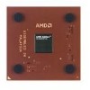
Page 43 highlights

24309E-March 2002 Preliminary Information AMD Athlon™ XP Processor Model 6 Data Sheet 7.9 VCC_CORE Voltage and Current Table 8 shows the voltage and current for the AMD Athlon XP processor model 6 during normal and reduced power states. Table 8. VCC_CORE Voltage and Current Model Number Frequency (MHz) Nominal Voltage Die Temperature ICC (Processor Current) Maximum Typical 1500+ 1333 34.3 A 30.8 A 1600+ 1400 35.9 A 32.2 A 1700+ 1467 36.6 A 32.8 A 1800+ 1533 1.75 90°C 37.7 A 33.8 A 1900+ 1600 38.9 A 34.7 A 2000+ 1667 40.0 A 35.7 A 2100+ 1733 41.1 A 36.7 A Stop Grant S1 or Sleep State1, 2, 3, 4, 5 1.30 V 50°C 1.54 A 0.66 A Notes: 1. The cooling fan can be turned off during the Sleep state, but customers should test their systems in Sleep state to ensure that the system, when using typical parts, has adequate cooling (without the fan during the Sleep state) to meet the temperature specification of the product. 2. See Figure 3, "AMD Athlon™ XP Processor Model 6 Power Management States" on page 9. 3. The maximum Stop Grant currents are absolute worst case currents for parts that may yield from the worst case corner of the process and are not representative of the typical Stop Grant current that is currently about one-third of the maximum specified current. 4. These currents occur when the AMD Athlon system bus is disconnected and a low power ratio of 1/64 is applied to the core clock grid of the processor as dictated by a value of 6003_D22Fh programmed into the Clock Control (CLK_Ctl) MSR. 5. The Stop Grant current consumption is characterized and not tested. Chapter 7 Electrical Data 31

  • 1
  • 2
  • 3
  • 4
  • 5
  • 6
  • 7
  • 8
  • 9
  • 10
  • 11
  • 12
  • 13
  • 14
  • 15
  • 16
  • 17
  • 18
  • 19
  • 20
  • 21
  • 22
  • 23
  • 24
  • 25
  • 26
  • 27
  • 28
  • 29
  • 30
  • 31
  • 32
  • 33
  • 34
  • 35
  • 36
  • 37
  • 38
  • 39
  • 40
  • 41
  • 42
  • 43
  • 44
  • 45
  • 46
  • 47
  • 48
  • 49
  • 50
  • 51
  • 52
  • 53
  • 54
  • 55
  • 56
  • 57
  • 58
  • 59
  • 60
  • 61
  • 62
  • 63
  • 64
  • 65
  • 66
  • 67
  • 68
  • 69
  • 70
  • 71
  • 72
  • 73
  • 74
  • 75
  • 76
  • 77
  • 78
  • 79
  • 80
  • 81
  • 82
  • 83
  • 84
  • 85
  • 86
  • 87
  • 88
  • 89
  • 90
  • 91
  • 92
  • 93
  • 94

Chapter 7
Electrical Data
31
24309E—March 2002
AMD Athlon™ XP Processor Model 6 Data Sheet
Preliminary Information
7.9
VCC_CORE Voltage and Current
Table 8 shows the voltage and current for the AMD Athlon XP
processor model 6 during normal and reduced power states.
Table 8.
VCC_CORE Voltage and Current
Model Number
Frequency (MHz)
Nominal Voltage
Die Temperature
I
CC
(
Processor Current
)
Maximum
Typical
1500+
1333
1.75
90
°
C
34.3 A
30.8 A
1600+
1400
35.9 A
32.2 A
1700+
1467
36.6 A
32.8 A
1800+
1533
37.7 A
33.8 A
1900+
1600
38.9 A
34.7 A
2000+
1667
40.0 A
35.7 A
2100+
1733
41.1 A
36.7 A
Stop Grant S1 or Sleep State
1, 2, 3, 4, 5
1.30 V
50
°
C
1.54 A
0.66 A
Notes:
1.
The cooling fan can be turned off during the Sleep state, but customers should test their systems in Sleep state to ensure that the
system, when using typical parts, has adequate cooling (without the fan during the Sleep state) to meet the temperature
specification of the product.
2.
See Figure 3, "AMD Athlon™ XP Processor Model 6 Power Management States" on page 9.
3.
The maximum Stop Grant currents are absolute worst case currents for parts that may yield from the worst case corner of the
process and are not representative of the typical Stop Grant current that is currently about one-third of the maximum specified
current.
4.
These currents occur when the AMD Athlon system bus is disconnected and a low power ratio of 1/64 is applied to the core clock
grid of the processor as dictated by a value of 6003_D22Fh programmed into the Clock Control (CLK_Ctl) MSR.
5.
The Stop Grant current consumption is characterized and not tested.