Acer Aspire 7736ZG Service Guide - Page 63
Removing the Optical Drive Module
 |
View all Acer Aspire 7736ZG manuals
Add to My Manuals
Save this manual to your list of manuals |
Page 63 highlights
NOTE: When installing the CPU, make sure to install the CPU with Pin 1 at the corner as shown. Removing the Optical Drive Module 1. See "Removing the SD Dummy Card" on page 44. 2. See "Removing the Battery Pack" on page 45. 3. See "Removing the Back Cover" on page 46. 4. See "Removing the Hard Disk Drive Module" on page 48. 5. See "Removing the Wireless LAN Card" on page 50. 6. See "Removing the DIMM Module" on page 51. 7. See "Removing the Heatsink Module" on page 52. 8. See "Removing the CPU" on page 54. 9. Remove the one screw (C) securing the optical drive module to the system. Size (Quantity) M2.5 x L6 (1) Chapter 3 Color Black Torque 3.0 kgf-cm Part No. 86.00E12.536 55
-
 1
1 -
2
-
3
-
4
-
5
-
6
-
7
-
8
-
9
-
10
-
11
-
12
-
13
-
14
-
15
-
16
-
17
-
18
-
19
-
20
-
21
-
22
-
23
-
24
-
25
-
26
-
27
-
28
-
29
-
30
-
31
-
32
-
33
-
34
-
35
-
36
-
37
-
38
-
39
-
40
-
41
-
42
-
43
-
44
-
45
-
46
-
47
-
48
-
49
-
50
-
51
-
52
-
53
-
54
-
55
-
56
-
57
-
 58
58 -
 59
59 -
 60
60 -
 61
61 -
 62
62 -
 63
63 -
 64
64 -
 65
65 -
 66
66 -
 67
67 -
 68
68 -
69
-
70
-
71
-
72
-
73
-
74
-
75
-
76
-
77
-
78
-
79
-
80
-
81
-
82
-
83
-
84
-
85
-
86
-
87
-
88
-
89
-
90
-
91
-
92
-
93
-
94
-
95
-
96
-
97
-
98
-
99
-
100
-
101
-
102
-
103
-
104
-
105
-
106
-
107
-
108
-
109
-
110
-
111
-
112
-
113
-
114
-
115
-
116
-
117
-
118
-
119
-
120
-
121
-
122
-
123
-
124
-
125
-
126
-
127
-
128
-
129
-
130
-
131
-
132
-
133
-
134
-
135
-
136
-
137
-
138
-
139
-
140
-
141
-
142
-
143
-
144
-
145
-
146
-
147
-
148
-
149
-
150
-
151
-
152
-
153
-
154
-
155
-
156
-
157
-
158
-
159
-
160
-
161
-
162
-
163
-
164
-
165
-
166
-
167
-
168
-
169
-
170
-
171
-
172
-
173
-
174
-
175
-
176
-
177
-
178
-
179
-
180
-
181
-
182
-
183
-
184
-
185
-
186
-
187
 |
 |
Chapter 3
55
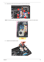
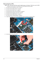
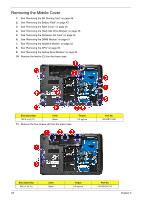
NOTE:
When installing the CPU, make sure to install the CPU with Pin 1 at the corner as shown.
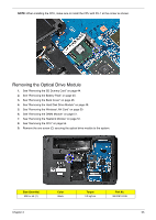
Removing the Optical Drive Module
1.
See “Removing the SD Dummy Card” on page 44.
2.
See “Removing the Battery Pack” on page 45.
3.
See “Removing the Back Cover” on page 46.
4.
See “Removing the Hard Disk Drive Module” on page 48.
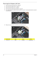
5.
See “Removing the Wireless LAN Card” on page 50.
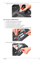
6.
See “Removing the DIMM Module” on page 51.
7.
See “Removing the Heatsink Module” on page 52.
8.
See “Removing the CPU” on page 54.
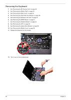
9.
Remove the one screw (C) securing the optical drive module to the system.
Size (Quantity)
Color
Torque
Part No.
M2.5 x L6 (1)
Black
3.0 kgf-cm
86.00E12.536