Acer Aspire 7736ZG Service Guide - Page 71
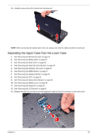
Separating the Upper Case from the Lower Case
 |
View all Acer Aspire 7736ZG manuals
Add to My Manuals
Save this manual to your list of manuals |
Page 71 highlights
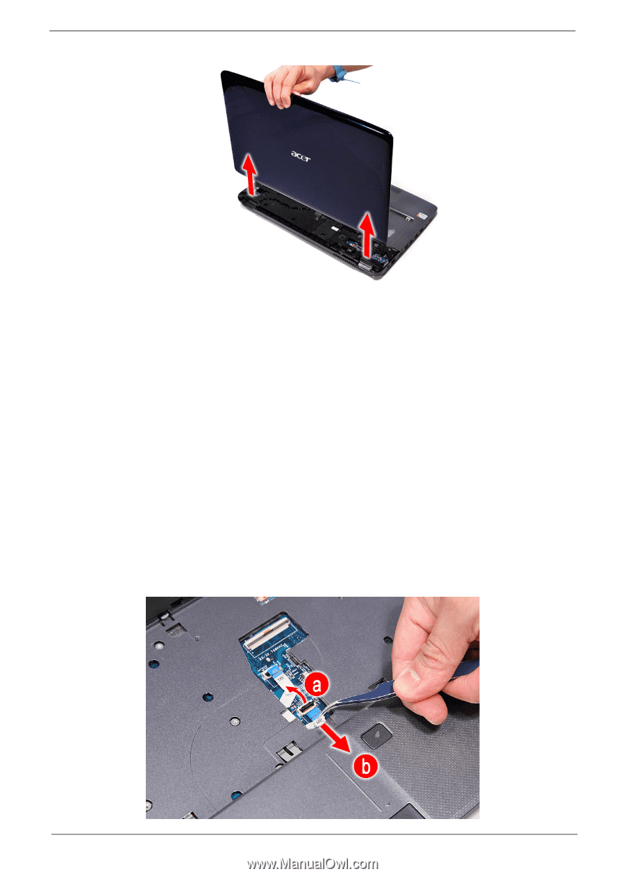
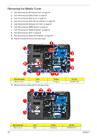
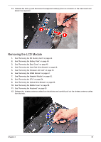
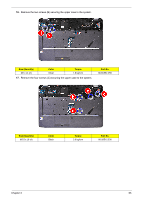
15. Carefully remove the LCD module from the base unit. NOTE: When connecting the cables back to the unit, please note that the cables should be routed well. Separating the Upper Case from the Lower Case 1. See "Removing the SD Dummy Card" on page 44. 2. See "Removing the Battery Pack" on page 45. 3. See "Removing the Back Cover" on page 46. 4. See "Removing the Hard Disk Drive Module" on page 48. 5. See "Removing the Wireless LAN Card" on page 50. 6. See "Removing the DIMM Module" on page 51. 7. See "Removing the Heatsink Module" on page 52. 8. See "Removing the CPU" on page 54. 9. See "Removing the Optical Drive Module" on page 55. 10. See "Removing the Middle Cover" on page 58. 11. See "Removing the Keyboard" on page 60. 12. See "Removing the LCD Module" on page 61. 13. Release the latch (a) and disconnect the fingerprint cable (b) from its connector on the main board. Chapter 3 63
-
 1
1 -
2
-
3
-
4
-
5
-
6
-
7
-
8
-
9
-
10
-
11
-
12
-
13
-
14
-
15
-
16
-
17
-
18
-
19
-
20
-
21
-
22
-
23
-
24
-
25
-
26
-
27
-
28
-
29
-
30
-
31
-
32
-
33
-
34
-
35
-
36
-
37
-
38
-
39
-
40
-
41
-
42
-
43
-
44
-
45
-
46
-
47
-
48
-
49
-
50
-
51
-
52
-
53
-
54
-
55
-
56
-
57
-
58
-
59
-
60
-
61
-
62
-
63
-
64
-
65
-
 66
66 -
 67
67 -
 68
68 -
 69
69 -
 70
70 -
 71
71 -
 72
72 -
 73
73 -
 74
74 -
 75
75 -
 76
76 -
77
-
78
-
79
-
80
-
81
-
82
-
83
-
84
-
85
-
86
-
87
-
88
-
89
-
90
-
91
-
92
-
93
-
94
-
95
-
96
-
97
-
98
-
99
-
100
-
101
-
102
-
103
-
104
-
105
-
106
-
107
-
108
-
109
-
110
-
111
-
112
-
113
-
114
-
115
-
116
-
117
-
118
-
119
-
120
-
121
-
122
-
123
-
124
-
125
-
126
-
127
-
128
-
129
-
130
-
131
-
132
-
133
-
134
-
135
-
136
-
137
-
138
-
139
-
140
-
141
-
142
-
143
-
144
-
145
-
146
-
147
-
148
-
149
-
150
-
151
-
152
-
153
-
154
-
155
-
156
-
157
-
158
-
159
-
160
-
161
-
162
-
163
-
164
-
165
-
166
-
167
-
168
-
169
-
170
-
171
-
172
-
173
-
174
-
175
-
176
-
177
-
178
-
179
-
180
-
181
-
182
-
183
-
184
-
185
-
186
-
187
 |
 |