Acer Aspire 7736ZG Service Guide - Page 89
Removing the LCD Brackets, Removing the Web Camera
 |
View all Acer Aspire 7736ZG manuals
Add to My Manuals
Save this manual to your list of manuals |
Page 89 highlights
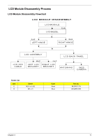
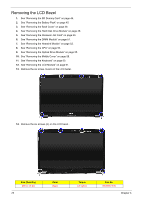
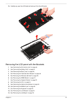
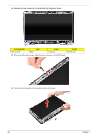
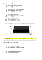
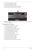
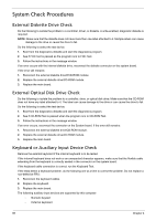
Removing the LCD Brackets 1. See "Removing the SD Dummy Card" on page 44. 2. See "Removing the Battery Pack" on page 45. 3. See "Removing the Back Cover" on page 46. 4. See "Removing the Hard Disk Drive Module" on page 48. 5. See "Removing the Wireless LAN Card" on page 50. 6. See "Removing the DIMM Module" on page 51. 7. See "Removing the Heatsink Module" on page 52. 8. See "Removing the CPU" on page 54. 9. See "Removing the Optical Drive Module" on page 55. 10. See "Removing the Middle Cover" on page 58. 11. See "Removing the Keyboard" on page 60. 12. See "Removing the LCD Module" on page 61. 13. See "Removing the LCD Bezel" on page 78. 14. See "Removing the LCD panel with the Brackets" on page 79. 15. Remove the six screws (H) securing the left and right LCD brackets to remove the brackets. Size (Quantity) M2 x L3 (6) Color Silver Torque Removing the Web Camera 1. See "Removing the SD Dummy Card" on page 44. 2. See "Removing the Battery Pack" on page 45. 3. See "Removing the Back Cover" on page 46. 4. See "Removing the Hard Disk Drive Module" on page 48. 5. See "Removing the Wireless LAN Card" on page 50. 6. See "Removing the DIMM Module" on page 51. 7. See "Removing the Heatsink Module" on page 52. 8. See "Removing the CPU" on page 54. 9. See "Removing the Optical Drive Module" on page 55. 10. See "Removing the Middle Cover" on page 58. Chapter 3 Part No. 86.9A552.3R0 81
-
 1
1 -
2
-
3
-
4
-
5
-
6
-
7
-
8
-
9
-
10
-
11
-
12
-
13
-
14
-
15
-
16
-
17
-
18
-
19
-
20
-
21
-
22
-
23
-
24
-
25
-
26
-
27
-
28
-
29
-
30
-
31
-
32
-
33
-
34
-
35
-
36
-
37
-
38
-
39
-
40
-
41
-
42
-
43
-
44
-
45
-
46
-
47
-
48
-
49
-
50
-
51
-
52
-
53
-
54
-
55
-
56
-
57
-
58
-
59
-
60
-
61
-
62
-
63
-
64
-
65
-
66
-
67
-
68
-
69
-
70
-
71
-
72
-
73
-
74
-
75
-
76
-
77
-
78
-
79
-
80
-
81
-
82
-
83
-
 84
84 -
 85
85 -
 86
86 -
 87
87 -
 88
88 -
 89
89 -
 90
90 -
 91
91 -
 92
92 -
 93
93 -
 94
94 -
95
-
96
-
97
-
98
-
99
-
100
-
101
-
102
-
103
-
104
-
105
-
106
-
107
-
108
-
109
-
110
-
111
-
112
-
113
-
114
-
115
-
116
-
117
-
118
-
119
-
120
-
121
-
122
-
123
-
124
-
125
-
126
-
127
-
128
-
129
-
130
-
131
-
132
-
133
-
134
-
135
-
136
-
137
-
138
-
139
-
140
-
141
-
142
-
143
-
144
-
145
-
146
-
147
-
148
-
149
-
150
-
151
-
152
-
153
-
154
-
155
-
156
-
157
-
158
-
159
-
160
-
161
-
162
-
163
-
164
-
165
-
166
-
167
-
168
-
169
-
170
-
171
-
172
-
173
-
174
-
175
-
176
-
177
-
178
-
179
-
180
-
181
-
182
-
183
-
184
-
185
-
186
-
187
 |
 |