Akai MPC1000 Operation Manual - Page 11
Front Panel, Rear Panel, Introduction - memory
 |
View all Akai MPC1000 manuals
Add to My Manuals
Save this manual to your list of manuals |
Page 11 highlights
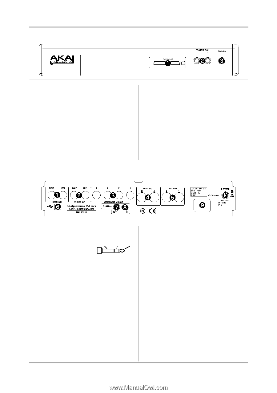
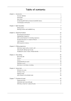
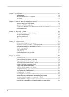
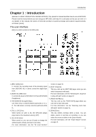
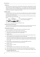
Front Panel Introduction 1. Compact flash slot: This is a card slot for the compact flash memory card. 2. [FOOTSWITCH 1/2] plug: This is where you connect a foot switch. You can use a foot switch to punch in/out. For more information, see the "Foot Switch" section on page 87. There are two types of foot switches: normal open (the contact is open when it is not pressed), and normal closed (the contact is closed when it is not pressed). If a foot switch has been connected to the MPC1000, when you turn on the power to the MPC1000, it automatically detects the type of foot switch connected. You can use either type of foot switch. 3. [PHONES] plug: This is a stereo phone plug to connect a set of headphones. It sends out the same signal with the [STEREO OUT] plug. Rear Panel 1. [RECORD IN L/R] plug: This is an analog input for recording an analog signal. With a stereo phone plug, it GND can be used as balanced input. COLD HOT 2. [STEREO OUT L/R] plug: This is the main output 3. [ASSIGNABLE MIX OUT 1/2/3/4] plug: These are outputs you can use to output each pad sound separately. With external mixers or effecters, you can perform advanced mixing. 4. [MIDI OUT A/B] plug: This is the MIDI output. Each output can send independent MIDI signals. 5. [MIDI IN 1/2] plug: This is the MIDI input. MIDI signals from MIDI IN 1 and 2 will be merged (mixed). 6. [USB] plug (slave): You use this plug to connect the MPC1000 to your PC and transfer data. For more information, see the "Connecting the MPC1000 to your computer" section on page 85. 7. [DIGITAL OUT] plug: This is the coaxial digital output. It sends out the same signal as the [STEREO OUT] plug. 8. [DIGITAL IN] plug: This is the coaxial digital input. Use this input to connect digital outputs such as a CD player and a DAT. 9. Power plug: Plug in the AC cable here. 10. [POWER] switch: It switches the power on/off of the unit. -3-
-
 1
1 -
2
-
3
-
4
-
5
-
 6
6 -
 7
7 -
 8
8 -
 9
9 -
 10
10 -
 11
11 -
 12
12 -
 13
13 -
 14
14 -
 15
15 -
 16
16 -
17
-
18
-
19
-
20
-
21
-
22
-
23
-
24
-
25
-
26
-
27
-
28
-
29
-
30
-
31
-
32
-
33
-
34
-
35
-
36
-
37
-
38
-
39
-
40
-
41
-
42
-
43
-
44
-
45
-
46
-
47
-
48
-
49
-
50
-
51
-
52
-
53
-
54
-
55
-
56
-
57
-
58
-
59
-
60
-
61
-
62
-
63
-
64
-
65
-
66
-
67
-
68
-
69
-
70
-
71
-
72
-
73
-
74
-
75
-
76
-
77
-
78
-
79
-
80
-
81
-
82
-
83
-
84
-
85
-
86
-
87
-
88
-
89
-
90
-
91
-
92
-
93
-
94
-
95
-
96
-
97
-
98
-
99
-
100
-
101
-
102
-
103
-
104
 |
 |