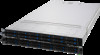
Asus RS700-E10-RS12U User Manual - Page 128
LAN activity LED connector LAN1_LED, LAN2_LED, Power Button/Soft-off Button connector PWRBTN
 |
View all Asus RS700-E10-RS12U manuals
Add to My Manuals
Save this manual to your list of manuals |
Page 128 highlights
14. System panel connector (10-1 pin SYS_PANEL1; 14-1 pin SYS_PANEL2) This connector supports several chassis-mounted functions. • System power LED (FP_PLED) This 1-pin connector is for the system power LED. Connect the chassis power LED cable to this connector. The system power LED lights up when you turn on the system power, and blinks when the system is in sleep mode. • Message LED (FP_MLED) This 1-pin connector is for the message LED cable that connects to the front message LED. The message LED is controlled by the BMC to indicate an abnormal event occurrence. • Locator LED connector (AUX_BMCLOCLED) This connector allows you to connect the Locator LED. The Location LED helps visually locate and identify the server in error on a server rack. • Power Button/Soft-off Button connector (PWRBTN) The 3-1 pin connector allows you to connect the system power button. Press the power button to power up the system, or put the system into sleep or soft-off mode (depending on the operating system settings). • LAN activity LED connector (LAN1_LED, LAN2_LED, LAN3_LED, LAN4_LED) This 2-pin connector allows you to connect the Gigabit LAN Activity LED. • Reset button connector (RESET) This connector allows you to connect the chassis-mounted reset button. Press the reset button to reboot the system. • TR1 Sensor connector (TR1 SENSOR) This connector allows detection of the environmental temperature of the front panel. 4-20 Chapter 4: Motherboard Information
-
 1
1 -
2
-
3
-
4
-
5
-
6
-
7
-
8
-
9
-
10
-
11
-
12
-
13
-
14
-
15
-
16
-
17
-
18
-
19
-
20
-
21
-
22
-
23
-
24
-
25
-
26
-
27
-
28
-
29
-
30
-
31
-
32
-
33
-
34
-
35
-
36
-
37
-
38
-
39
-
40
-
41
-
42
-
43
-
44
-
45
-
46
-
47
-
48
-
49
-
50
-
51
-
52
-
53
-
54
-
55
-
56
-
57
-
58
-
59
-
60
-
61
-
62
-
63
-
64
-
65
-
66
-
67
-
68
-
69
-
70
-
71
-
72
-
73
-
74
-
75
-
76
-
77
-
78
-
79
-
80
-
81
-
82
-
83
-
84
-
85
-
86
-
87
-
88
-
89
-
90
-
91
-
92
-
93
-
94
-
95
-
96
-
97
-
98
-
99
-
100
-
101
-
102
-
103
-
104
-
105
-
106
-
107
-
108
-
109
-
110
-
111
-
112
-
113
-
114
-
115
-
116
-
117
-
118
-
119
-
120
-
121
-
122
-
 123
123 -
 124
124 -
 125
125 -
 126
126 -
 127
127 -
 128
128 -
 129
129 -
 130
130 -
 131
131 -
 132
132 -
 133
133 -
134
-
135
-
136
-
137
-
138
-
139
-
140
-
141
-
142
-
143
-
144
-
145
-
146
-
147
-
148
-
149
-
150
-
151
-
152
-
153
-
154
-
155
-
156
-
157
-
158
-
159
-
160
-
161
-
162
-
163
-
164
-
165
-
166
-
167
-
168
-
169
-
170
-
171
-
172
-
173
-
174
-
175
-
176
-
177
-
178
-
179
-
180
-
181
-
182
-
183
-
184
-
185
-
186
-
187
-
188
-
189
-
190
-
191
-
192
-
193
-
194
-
195
-
196
-
197
-
198
-
199
-
200
-
201
-
202
-
203
-
204
-
205
-
206
-
207
-
208
-
209
-
210
-
211
-
212
 |
 |
