Asus RS700-E10-RS12U User Manual - Page 17
Front panel features, 1.5 Rear panel features
 |
View all Asus RS700-E10-RS12U manuals
Add to My Manuals
Save this manual to your list of manuals |
Page 17 highlights
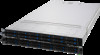
1.4 Front panel features The barebone server displays a simple yet stylish front panel with easily accessible features. The power and reset buttons, LED indicators are located on the front panel. Refer to section 1.7 LED information for the LED descriptions. Rack screw Bay 1 Bay 3 Bay 5 Bay 7 Bay 10 Bay 12 Bay 9 Bay 11 Rack screw Bay 2 Bay 4 Asset tag Bay 6 Bay 8 Power button Power LED LAN1 and LAN3 LED LAN2 and LAN4 LED Location LED Reset button Message LED Location button • Bay 1 to bay 8 supports NVMe/SATA by default. SAS support requires optional ASUS PIKE II card. • Bay 9 to bay 12 supports NVMe/SATA by default (supports tri-mode card). • All bays support 2.5" drives with trays. 1.5 Rear panel features The rear panel includes the expansion slots, and system power sockets. The middle part includes the I/O shield with openings for the rear panel connectors on the motherboard. Management LAN port 1* Expansion slot Expansion slot Redundant Power supply and Power cord connector USB 3.2 Gen 1 ports Expansion slot VGA port Power button Location button Optional LAN port expansion slots Q-Code LED Optional External Fan location (for GPU) *This port is for ASUS ASMB10-iKVM only. ASUS RS700-E10 Series 1-7
-
 1
1 -
2
-
3
-
4
-
5
-
6
-
7
-
8
-
9
-
10
-
11
-
 12
12 -
 13
13 -
 14
14 -
 15
15 -
 16
16 -
 17
17 -
 18
18 -
 19
19 -
 20
20 -
 21
21 -
 22
22 -
23
-
24
-
25
-
26
-
27
-
28
-
29
-
30
-
31
-
32
-
33
-
34
-
35
-
36
-
37
-
38
-
39
-
40
-
41
-
42
-
43
-
44
-
45
-
46
-
47
-
48
-
49
-
50
-
51
-
52
-
53
-
54
-
55
-
56
-
57
-
58
-
59
-
60
-
61
-
62
-
63
-
64
-
65
-
66
-
67
-
68
-
69
-
70
-
71
-
72
-
73
-
74
-
75
-
76
-
77
-
78
-
79
-
80
-
81
-
82
-
83
-
84
-
85
-
86
-
87
-
88
-
89
-
90
-
91
-
92
-
93
-
94
-
95
-
96
-
97
-
98
-
99
-
100
-
101
-
102
-
103
-
104
-
105
-
106
-
107
-
108
-
109
-
110
-
111
-
112
-
113
-
114
-
115
-
116
-
117
-
118
-
119
-
120
-
121
-
122
-
123
-
124
-
125
-
126
-
127
-
128
-
129
-
130
-
131
-
132
-
133
-
134
-
135
-
136
-
137
-
138
-
139
-
140
-
141
-
142
-
143
-
144
-
145
-
146
-
147
-
148
-
149
-
150
-
151
-
152
-
153
-
154
-
155
-
156
-
157
-
158
-
159
-
160
-
161
-
162
-
163
-
164
-
165
-
166
-
167
-
168
-
169
-
170
-
171
-
172
-
173
-
174
-
175
-
176
-
177
-
178
-
179
-
180
-
181
-
182
-
183
-
184
-
185
-
186
-
187
-
188
-
189
-
190
-
191
-
192
-
193
-
194
-
195
-
196
-
197
-
198
-
199
-
200
-
201
-
202
-
203
-
204
-
205
-
206
-
207
-
208
-
209
-
210
-
211
-
212
 |
 |
