Asus VIA User Manual - Page 12
Motherboard Components - chipset
 |
View all Asus VIA manuals
Add to My Manuals
Save this manual to your list of manuals |
Page 12 highlights
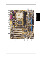
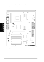
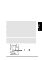
2. FEATURES MB Components 2. FEATURES 2.2 Motherboard Components See opposite page for locations. Location Processor Support Socket A for Socket A AMD Athlon/Duron Processors 3 (NOTE: Starting with PCB Rev. 1.02, the CPU thermal sensor is integrated on the motherboard, located near the center of the CPU heat source, just below the CPU socket) Feature Setting DIP Switches 6 Chipsets VIA VT8363 (VIA Apollo KT133) system controller 2 VIA VT82C686A PCIset 16 2Mbit Programmable Flash EEPROM 11 Main Memory Maximum 1.5GB support 3 DIMM Sockets 4 VC133/PC133 memory support Expansion Slots 5 PCI Slots 19 1 Accelerated Graphics Port (AGP) Pro Slot 22 1 Audio Modem Riser (AMR) Slot Shared) 18 System I/O 1 Floppy Disk Driver Connector 8 2 IDE Connectors (UltraDMA/66 Support 7 2 IDE Connectors (UltraDMA/100 Support 9 1 Parallel Port Connector Top) 26 1 Serial COM1 Port Connector Bottom) 27 1 Serial COM2 Port Connector Bottom) 25 USB Connectors (Port 0 & Port 1 28 USB Connectors (Port 2 & Port 3 14 USB Connectors (Ports 4-6 12 1 PS/2 Mouse Connector Top) 29 1 PS/2 Keyboard Connector Bottom) 29 Audio AC'97 V2.1 Audio Codec (optional 20 1 Game/MIDI Connector (on audio model only Top) 23 1 Line Out Connector (on audio model only) ........ (Bottom) 23 1 Line In Connector (on audio model only Bottom) 23 1 Microphone Connector (on audio model only) ... (Bottom) 23 Network Features Wake-On-LAN Connector 17 Wake-On-Ring Connector 13 Hardware Monitoring System Voltage Monitoring (integrated in ASUS ASIC) ....... 15 3 Fan Power and Speed Monitoring Connectors Power ATX Power Supply Connector 5 Special Feature Onboard LED 21 Promise® Ultra DMA/100 Chip 10 VRM Module 1 Form Factor ATX 12 ASUS A7V User's Manual
-
 1
1 -
2
-
3
-
4
-
5
-
6
-
 7
7 -
 8
8 -
 9
9 -
 10
10 -
 11
11 -
 12
12 -
 13
13 -
 14
14 -
 15
15 -
 16
16 -
 17
17 -
18
-
19
-
20
-
21
-
22
-
23
-
24
-
25
-
26
-
27
-
28
-
29
-
30
-
31
-
32
-
33
-
34
-
35
-
36
-
37
-
38
-
39
-
40
-
41
-
42
-
43
-
44
-
45
-
46
-
47
-
48
-
49
-
50
-
51
-
52
-
53
-
54
-
55
-
56
-
57
-
58
-
59
-
60
-
61
-
62
-
63
-
64
-
65
-
66
-
67
-
68
-
69
-
70
-
71
-
72
-
73
-
74
-
75
-
76
-
77
-
78
-
79
-
80
-
81
-
82
-
83
-
84
-
85
-
86
-
87
-
88
-
89
-
90
-
91
-
92
-
93
-
94
-
95
-
96
-
97
-
98
-
99
-
100
 |
 |