Asus VIA User Manual - Page 39
ASUS A7V User's Manual, USB Headers 5-1 pin USB3A, 10-1 pin USBPORT/USB3, SMBus Connector 5-1 pin
 |
View all Asus VIA manuals
Add to My Manuals
Save this manual to your list of manuals |
Page 39 highlights
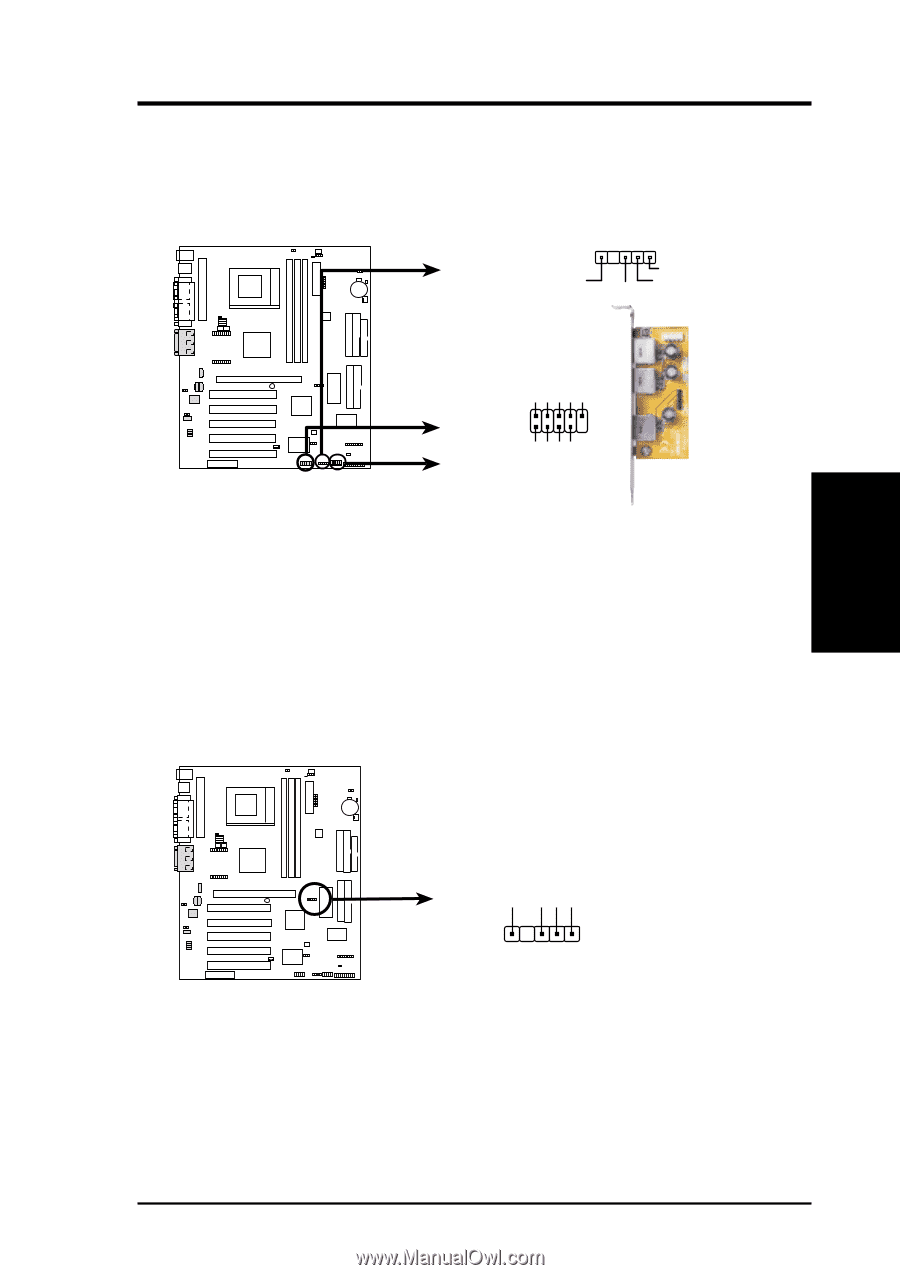
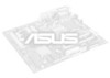
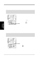
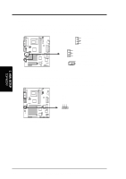
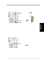
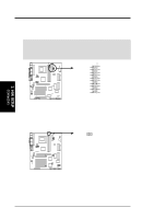
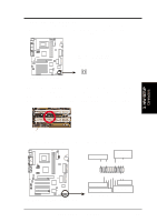
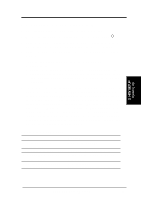
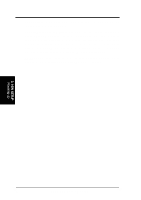
3. H/W SETUP Connectors 01 01 01 01 01 01 3. HARDWARE SETUP 17) USB Headers (5-1 pin USB3A, 10-1 pin USBPORT/USB3) (optional) If the USB port connectors on the back panel are inadequate, three USB headers are available for five additional USB port connectors. Connect the USB headers to an optional 3-port USB connector set and mount the bracket to an open slot on your chassis. 1 USB3A GND (Optional) USB Power USBP- USBP+ USB Power USBP2- USBP2+ GND NC USB Power USBP3- USBP3+ GND A7V A7V USB Ports 1 USBPORT 6 USB3 (Optional) 5 10 Bundled 3-port USB Connector Set Recommended Setup: Use USBPORT + USB3A with the bundled 3-port connector set. 18) SMBus Connector (5-1 pin SMB) This connector allows you to connect SMBus (System Management Bus) devices. SMBus devices communicate by means of the SMBus with an SMBus host and/or other SMBus devices. SMBus is a specific implementation of an I2C bus, which is a multi-device bus; that is, multiple chips can be connected to the same bus and each one can act as a master by initiating data transfer. SMBCLK Ground SMBDATA +5V A7V A7V SMBus Connector 1 SMB ASUS A7V User's Manual 39
-
 1
1 -
2
-
3
-
4
-
5
-
6
-
7
-
8
-
9
-
10
-
11
-
12
-
13
-
14
-
15
-
16
-
17
-
18
-
19
-
20
-
21
-
22
-
23
-
24
-
25
-
26
-
27
-
28
-
29
-
30
-
31
-
32
-
33
-
 34
34 -
 35
35 -
 36
36 -
 37
37 -
 38
38 -
 39
39 -
 40
40 -
 41
41 -
 42
42 -
 43
43 -
 44
44 -
45
-
46
-
47
-
48
-
49
-
50
-
51
-
52
-
53
-
54
-
55
-
56
-
57
-
58
-
59
-
60
-
61
-
62
-
63
-
64
-
65
-
66
-
67
-
68
-
69
-
70
-
71
-
72
-
73
-
74
-
75
-
76
-
77
-
78
-
79
-
80
-
81
-
82
-
83
-
84
-
85
-
86
-
87
-
88
-
89
-
90
-
91
-
92
-
93
-
94
-
95
-
96
-
97
-
98
-
99
-
100
 |
 |