Asus VIA User Manual - Page 18
H/w Setup
 |
View all Asus VIA manuals
Add to My Manuals
Save this manual to your list of manuals |
Page 18 highlights
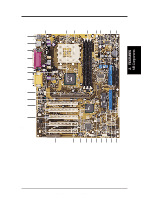
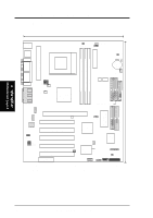
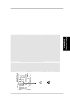
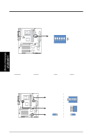
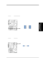
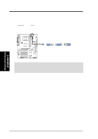
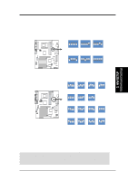
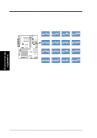
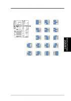
3. H/W SETUP Motherboard Settings 3. HARDWARE SETUP 1) Motherboard Features Settings (DIP Switches - DSW) The motherboard's onboard functions are adjusted through the DIP switches The white block represents the switch's position. The default setting is OFF. Note:The diagram pictures Printed Circuit Board (PCB) 1.04, which has 5 DIP switches. PCB 1.02 has 4 DIP switches. The defaults shown below are identical for both versions. 01 01 01 01 01 01 A7V A7V DIP Switches DSW 54 321 OFF ON ON 1. Frequency Selection 2. Frequency Selection 3. Frequency Selection 4. Frequency Selection 5. Frequency Selection 2) JumperFree™ Mode (JEN) This jumper allows you to enable or disable the JumperFree™ mode. The JumperFree™ mode allows processor settings to be made through the BIOS setup (see 4.4 Advanced Menu). Setting Jumper Mode DSW (See #6 External Frequency Setting) JumperFree™Mode All OFF VID JEN (See #8 Voltage [1-2] Regulator Output) All [3-4] [2-3](Default) A7V A7V Jumper Mode Settings Jumper Mode JumperFree Mode (Default) See External Frequency Setting DSW 54 3 2 1 OFF ON ON See Voltage Reg. Out. (VID) 1234 VID4 VID3 VID2 VID1 JEN 12 JEN 23 18 ASUS A7V User's Manual
-
 1
1 -
2
-
3
-
4
-
5
-
6
-
7
-
8
-
9
-
10
-
11
-
12
-
 13
13 -
 14
14 -
 15
15 -
 16
16 -
 17
17 -
 18
18 -
 19
19 -
 20
20 -
 21
21 -
 22
22 -
 23
23 -
24
-
25
-
26
-
27
-
28
-
29
-
30
-
31
-
32
-
33
-
34
-
35
-
36
-
37
-
38
-
39
-
40
-
41
-
42
-
43
-
44
-
45
-
46
-
47
-
48
-
49
-
50
-
51
-
52
-
53
-
54
-
55
-
56
-
57
-
58
-
59
-
60
-
61
-
62
-
63
-
64
-
65
-
66
-
67
-
68
-
69
-
70
-
71
-
72
-
73
-
74
-
75
-
76
-
77
-
78
-
79
-
80
-
81
-
82
-
83
-
84
-
85
-
86
-
87
-
88
-
89
-
90
-
91
-
92
-
93
-
94
-
95
-
96
-
97
-
98
-
99
-
100
 |
 |
