Asus VIA User Manual - Page 35
ASUS A7V User's Manual, Chassis Intrusion Lead 2 pin CHASSIS, Standard and Consumer Infrared Module
 |
View all Asus VIA manuals
Add to My Manuals
Save this manual to your list of manuals |
Page 35 highlights
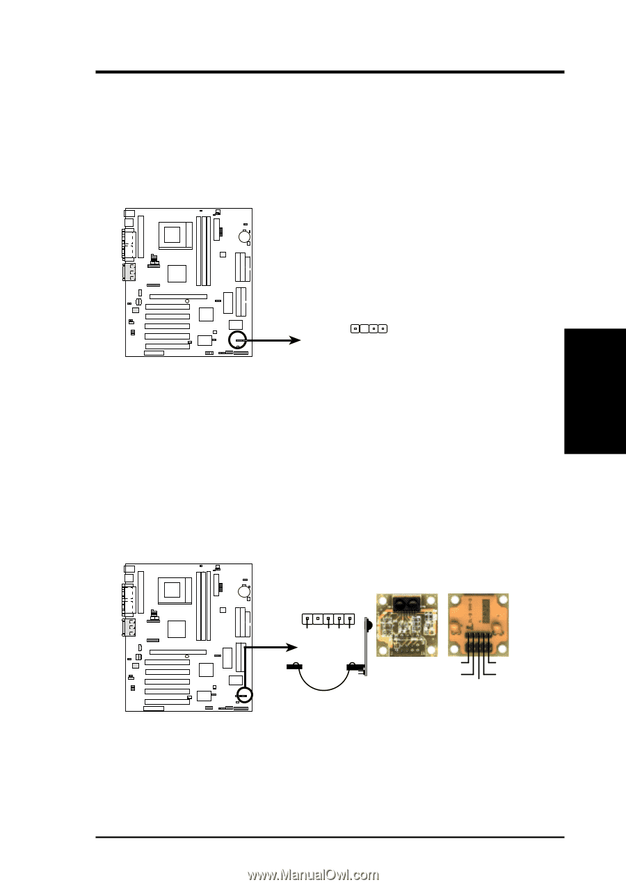
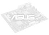
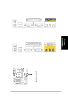
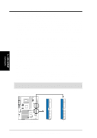
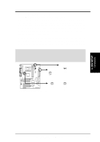
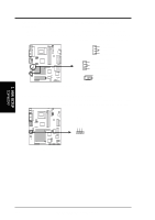
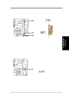
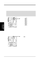
3. HARDWARE SETUP 10) Chassis Intrusion Lead (2 pin CHASSIS) This requires an external detection mechanism such as a chassis intrusion monitor/sensor or microswitch. The sensor is triggered when a high level signal is sent to the Chassis Signal lead, which occurs when a panel switch or light detector is triggered. This function requires the optional ASUS CIDB chassis intrusion module to be installed (see 7. APPENDIX). If the chassis intrusion lead is not used, a jumper cap must be placed over the pins to close the circuit. +5V IRRX GND IRTX 3. H/W SETUP Connectors 01 01 01 01 01 01 A7V A7V Chassis Open Alarm Lead 1 CHASSIS 11) Standard and Consumer Infrared Module Connector (5-pin IR) This connector supports an optional wireless transmitting and receiving infrared module. This module mounts to a small opening on system cases that support this feature. You must also configure the setting through UART2 Use Infrared (see 4.4.2 I/O Device Configuration) to select whether UART2 is directed for use with COM2 or IrDA. Use the five pins as shown in Back View and connect a ribbon cable from the module to the motherboard's SIR connector according to the pin definitions. IR 1 Front View Back View A7V A7V Infrared Module Connector IRTX GND IRRX +5V (NC) ASUS A7V User's Manual 35
-
 1
1 -
2
-
3
-
4
-
5
-
6
-
7
-
8
-
9
-
10
-
11
-
12
-
13
-
14
-
15
-
16
-
17
-
18
-
19
-
20
-
21
-
22
-
23
-
24
-
25
-
26
-
27
-
28
-
29
-
 30
30 -
 31
31 -
 32
32 -
 33
33 -
 34
34 -
 35
35 -
 36
36 -
 37
37 -
 38
38 -
 39
39 -
 40
40 -
41
-
42
-
43
-
44
-
45
-
46
-
47
-
48
-
49
-
50
-
51
-
52
-
53
-
54
-
55
-
56
-
57
-
58
-
59
-
60
-
61
-
62
-
63
-
64
-
65
-
66
-
67
-
68
-
69
-
70
-
71
-
72
-
73
-
74
-
75
-
76
-
77
-
78
-
79
-
80
-
81
-
82
-
83
-
84
-
85
-
86
-
87
-
88
-
89
-
90
-
91
-
92
-
93
-
94
-
95
-
96
-
97
-
98
-
99
-
100
 |
 |